Recessed luminaire

a recessed luminaire and recessed technology, applied in the direction of fixed installation, lighting and heating apparatus, lighting support devices, etc., can solve the problems of short circuit or contact failure, fire may spread to the apparatus main body, etc., to prevent fire spread, safe recessed luminaire, and efficient attachment operation

Inactive Publication Date: 2010-05-27
TOSHIBA LIGHTING & TECH CORP +1
View PDF50 Cites 26 Cited by
  • Summary
  • Abstract
  • Description
  • Claims
  • Application Information

AI Technical Summary

Benefits of technology

[0010]The present invention prevents the spread of fire resulting from, for example, overheating of the terminal base, so that a safe recessed luminaire can be provided. Further, the present invention prevents dust or the like from intruding into the terminal base.
[0011]Further, the present invention prevents fire from spreading to the apparatus main body.
[0012]Furthermore, the present invention allows the operator to attach the luminaire while visually observing an extending part of the terminal base attachment member after operating engaging means. Accordingly, the attachment operation can be efficiently performed.

Problems solved by technology

However, in the conventional luminaire mentioned above, dust or moisture may intrude into the terminal base, and a short circuit or contact failure may occur.
Particularly, if the terminal base is made of synthetic resin or the like, it may be melted or catch fire and the fire may spread to the apparatus main body.

Method used


Image

  • Recessed luminaire
  • Recessed luminaire
  • Recessed luminaire

Examples


Embodiment Construction

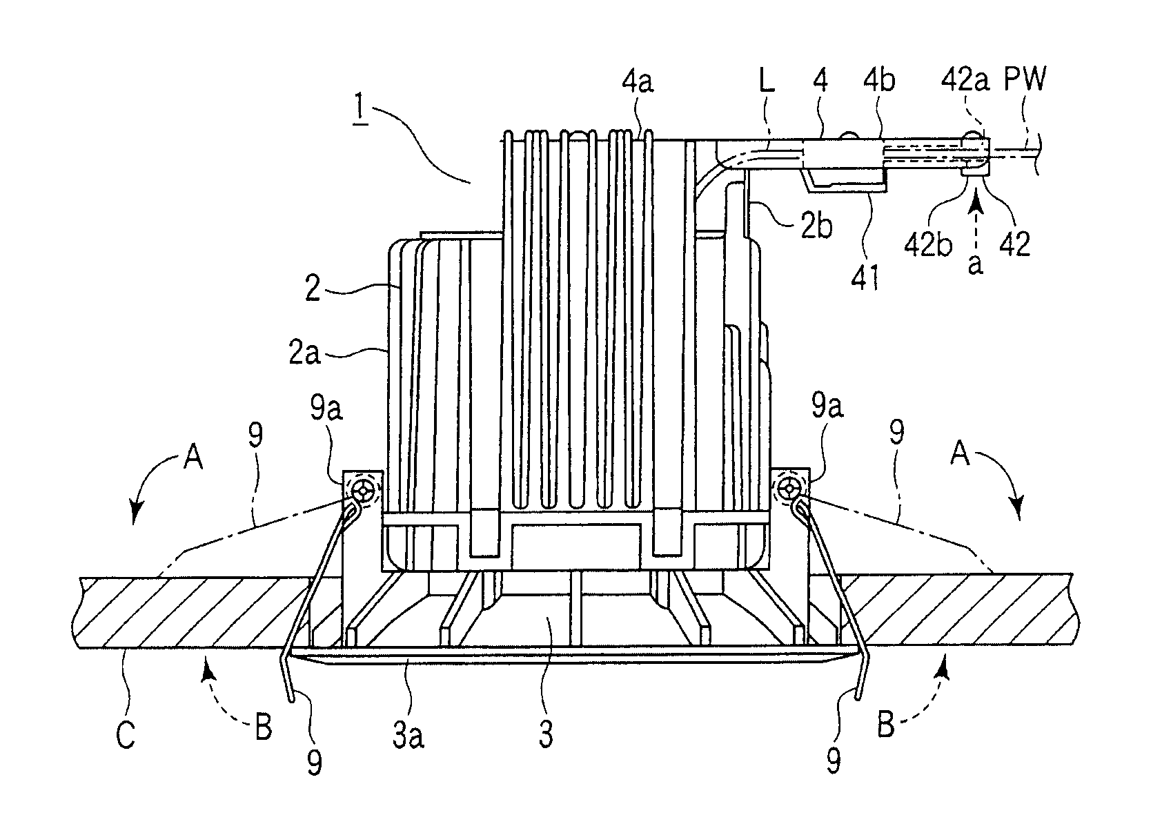
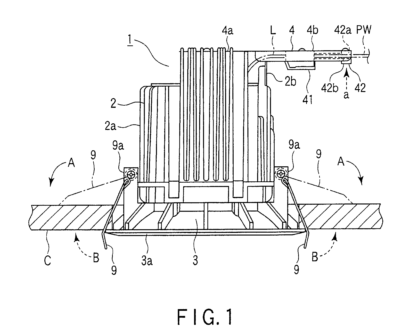
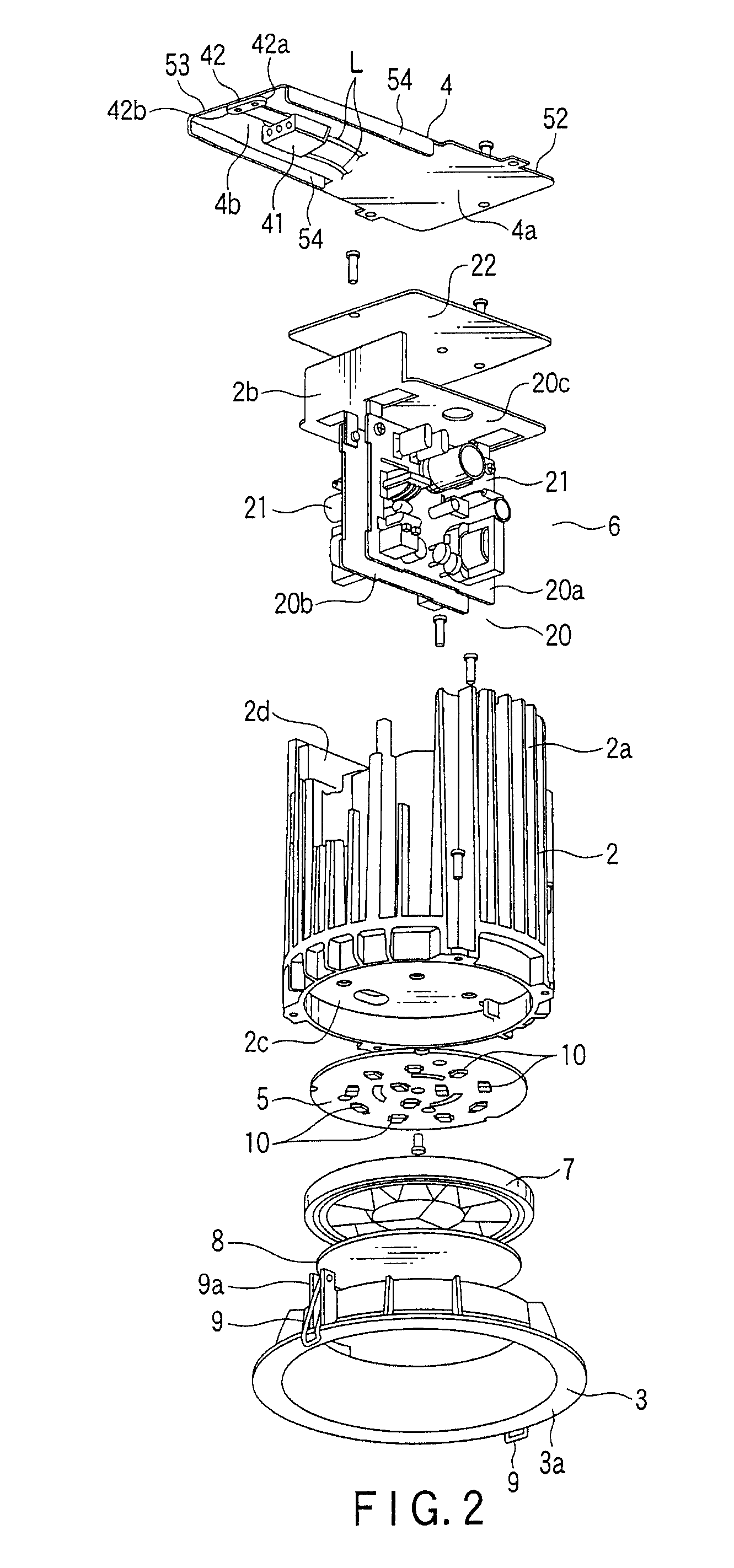
[0022]A recessed luminaire according to an embodiment of the present invention will be described below with reference to FIGS. 1 to 6. FIG. 1 is a side view showing a downlight as the recessed luminaire, FIG. 2 is an exploded perspective view of the downlight, FIG. 3 is a partially sectioned side view of the same, FIG. 4 is a top view of the same and FIG. 6 is a bottom view of the same.

[0023]The drawings show a recessed downlight as the recessed luminaire. A downlight main body 1 comprises a cylindrical body 2 which has a thermal conductivity, a decorative frame 3 and a terminal base attachment member 4 which are attached to the cylindrical body 2, a substrate 5 which is also attached to the cylindrical body 2 and on which LEDs (light-emitting devices) 10 as a light source are mounted, a power supply unit 6 including a power supply circuit board 20 contained in the cylindrical body 2, a reflector 7, and a translucent cover 8 attached in front of the reflector 7.

[0024]The cylindrical...


PUM


Abstract

A recessed luminaire includes a main body including a light source, a terminal base attachment member, which is fire-resistant and extending laterally from the main body, and a terminal base, which is disposed on a lower surface of the terminal base attachment member and to which power wires extending in parallel in a direction of extension of the terminal base attachment member are connected.

Description

CROSS-REFERENCE TO RELATED APPLICATIONS[0001]This application is based upon and claims the benefit of priority from prior Japanese Patent Application No. 2008-300058, filed Nov. 25, 2008, the entire contents of which are incorporated herein by reference.BACKGROUND OF THE INVENTION[0002]1. Field of the Invention[0003]The present invention relates to a recessed luminaire adapted for use in a recessed state in a ceiling or the like.[0004]2. Description of the Related Art[0005]As disclosed in Jpn. Pat. Appln. KOKAI Publication No. 2006-172895, a recessed luminaire comprises a terminal base connected to a power supply line to supply power to a light source. The terminal base and the power source are connected by a lead wire or the like, so that power is supplied to the light source. Conventionally, a type of recessed luminaire is known, in which the terminal base is directly attached to the main body of the luminaire or contained in the main body.[0006]However, in the conventional lumina...

Claims


Application Information

Patent Timeline
Patent Type & Authority Applications(United States)
IPC IPC(8): F21V15/00
CPCF21S8/026F21V21/04F21V23/006F21V25/12F21Y2101/02F21V23/02F21Y2115/10
Inventor HASHIMOTO, SUMIOMORIYAMA, TAKAYOSHIHIGUCHI, KAZUNARI
Owner TOSHIBA LIGHTING & TECH CORP
Why Eureka
Try Eureka