Systems and methods for constant voltage mode and constant current mode in flyback power converter with primary-side sensing and regulation

a technology of constant current mode and flyback power converter, which is applied in the field of integrated circuits, can solve the problems of increasing system cost, difficulty in compensating voltage drop due to cable loss, and poor control scheme of output voltage, so as to reduce system cost, improve reliability and/or efficiency, and reduce the effect of parts coun

Active Publication Date: 2010-05-27
ON BRIGHT ELECTRONICS SHANGHAI
View PDF19 Cites 141 Cited by
  • Summary
  • Abstract
  • Description
  • Claims
  • Application Information

AI Technical Summary

Benefits of technology

The present invention has several advantages compared to traditional methods. It reduces parts counts and lowers costs, improves reliability and efficiency, simplifies circuit designs for switch mode flyback power converters, provides better load regulation through a primary side sensing and regulation scheme, and ensures consistent output currents regardless of variations in primary winding inductance or other factors. These technical features make it easier to develop high-quality products with improved performance and stability.

Problems solved by technology

The present invention addresses the problem of poor regulation of output voltage and output current in switch-mode flyback power converters due to changes in the forward voltage of diodes and the inductance of the primary windings. The invention provides systems and methods for constant voltage mode and constant current mode, and compensating for changes in the output current through the use of primary-winding inductance compensation.

Method used


Image

  • Systems and methods for constant voltage mode and constant current mode in flyback power converter with primary-side sensing and regulation
  • Systems and methods for constant voltage mode and constant current mode in flyback power converter with primary-side sensing and regulation
  • Systems and methods for constant voltage mode and constant current mode in flyback power converter with primary-side sensing and regulation

Examples


Embodiment Construction

[0052]The present invention is directed to integrated circuits. More particularly, the invention provides systems and methods for constant voltage mode and constant current mode. Merely by way of example, the invention has been applied to a flyback power converter with primary-side sensing and regulation. But it would be recognized that the invention has a much broader range of applicability.

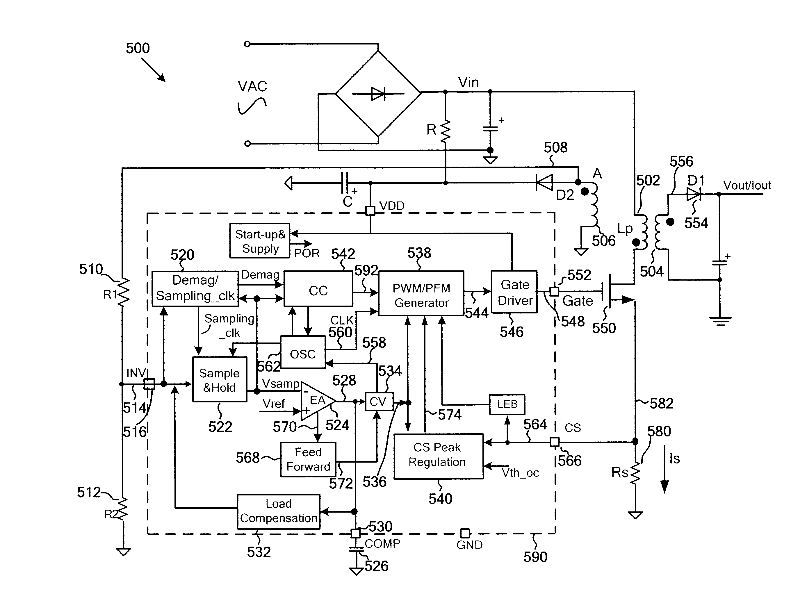
[0053]FIG. 5 is a simplified diagram for a switch-mode power conversion system with primary-side sensing and regulation according to an embodiment of the present invention. This diagram is merely an example, which should not unduly limit the scope of the claims. One of ordinary skill in the art would recognize many variations, alternatives, and modifications.

[0054]A switch-mode power conversion system 500 includes a primary winding 502, a secondary winding 504, and an auxiliary winding 506. Additionally, the conversion system 500 includes resistors 510, 512, and 580. Moreover, the conversion sys...


PUM


Abstract

System and method for regulating a power converter. The system includes a first signal generator configured to receive at least an input signal and generate at least a first output signal associated with demagnetization and a second output signal associated with sampling. Additionally, the system includes a sampling component configured to receive at least the input signal and the second output signal, sample the input signal based on at least information associated with the second output signal, and generate at least a third output signal associated with one or more sampled magnitudes. Moreover, the system includes an error amplifier configured to receive at least the third output signal and a first threshold voltage and generate at least a fourth output signal with a capacitor, the capacitor being coupled to the error amplifier.

Description


Claims


Application Information

Patent Timeline
Owner ON BRIGHT ELECTRONICS SHANGHAI
Why Eureka
Try Eureka