Image forming apparatus and method for controlling same

a technology of image forming apparatus and control method, which is applied in the direction of electrographic process apparatus, instruments, optics, etc., can solve the problems of deteriorating image quality, unstable output voltage of dc voltage application portion, damage to photoconductive drum, etc., and achieves the effect of increasing sensitivity

Active Publication Date: 2010-05-27
KYOCERA DOCUMENT SOLUTIONS INC
View PDF4 Cites 45 Cited by
  • Summary
  • Abstract
  • Description
  • Claims
  • Application Information

AI Technical Summary

Benefits of technology

[0012]This makes it possible to make the DC voltage application portion operate in a stable manner during printing, and to detect occurrence of electric discharge with increased sensitivity during electric discharge detection.

Problems solved by technology

When electric discharge occurs, due to a potential change on the surface of the photoconductive drum, the static latent image is disturbed, and the quality of the image formed is deteriorated.
When a large current flows, the photoconductive drum may suffer damage, such as a minute hole (pinhole) developing in it.
As the resistance value of the resistor is increased, however, when, during printing, there is a change in the potential of the developing roller, such as a rise in the potential due to an external factor, there appears a large change in a feedback voltage fed to a direct-current (DC) application portion that applies a DC voltage to the developing roller.
As a result, the DC voltage application portion stops outputting or reduces an output voltage, causing a problem that the output voltage of the DC voltage application portion becomes unstable.
When the output voltage of the DC voltage application portion becomes unstable, there arises a problem that may affect the quality of images, such as an error in the density of the images to be formed.
Accordingly, with the conventional developing units, it is impossible to solve the above-described problems.

Method used


Image

  • Image forming apparatus and method for controlling same
  • Image forming apparatus and method for controlling same
  • Image forming apparatus and method for controlling same

Examples


Embodiment Construction

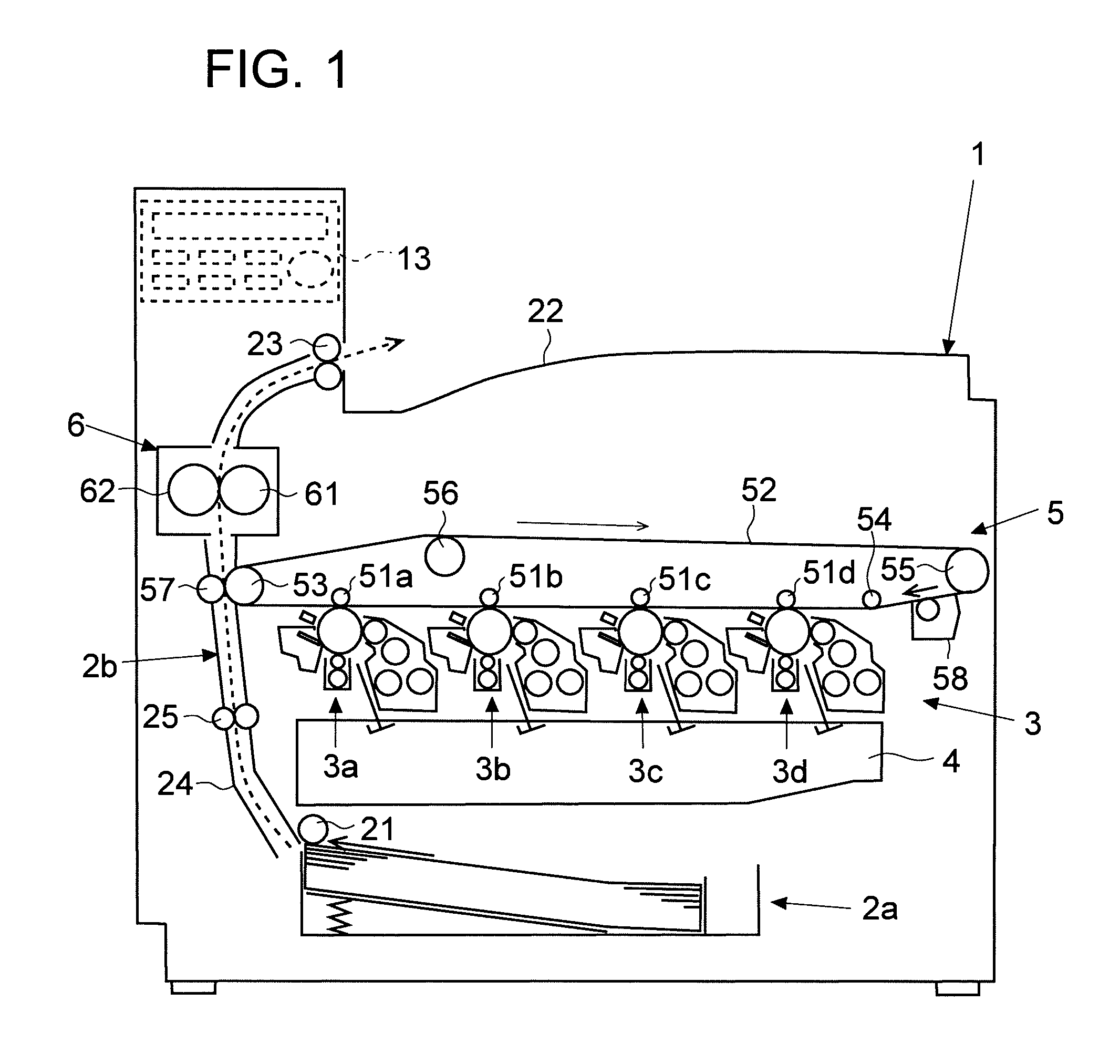
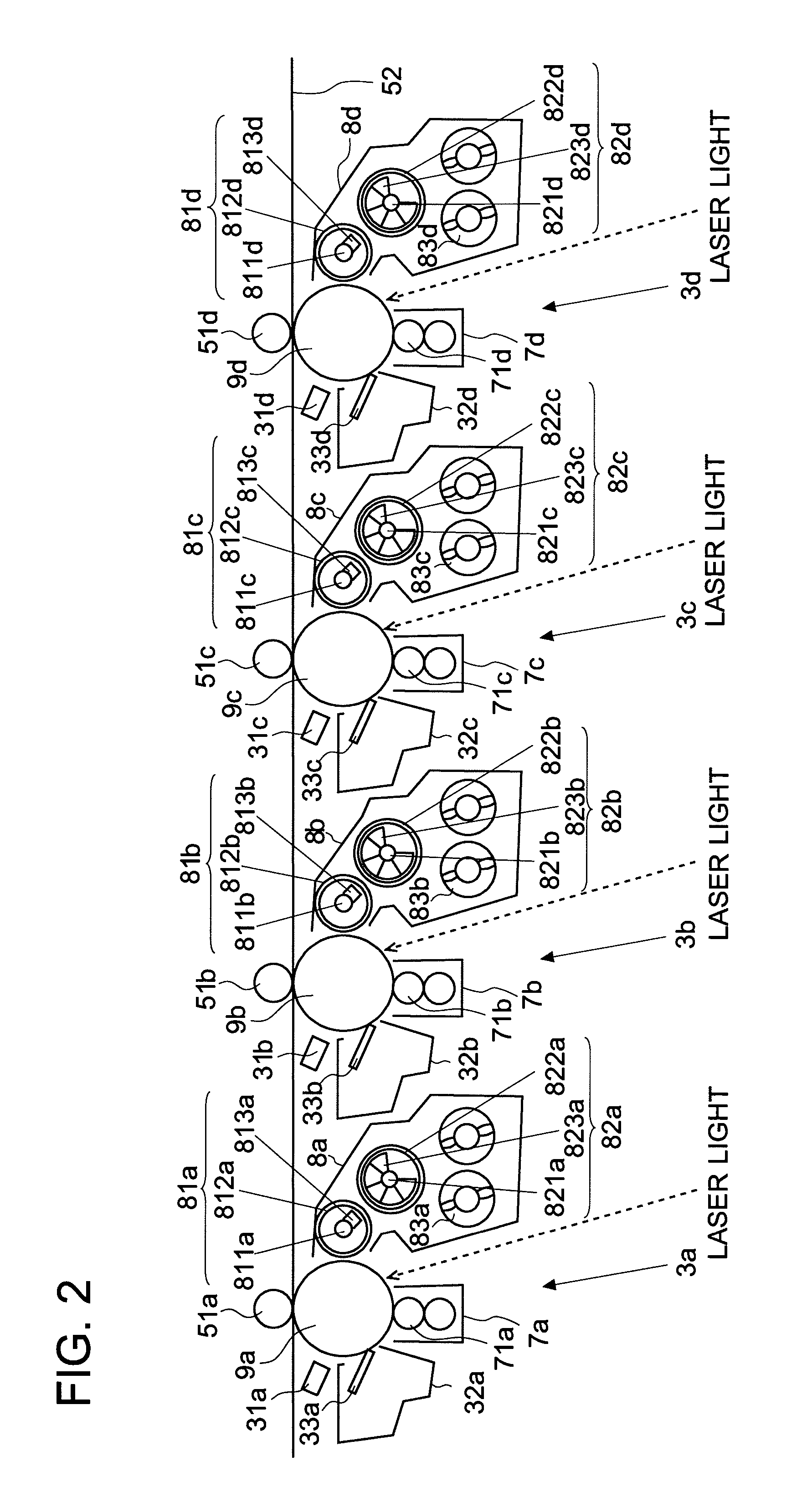
[0023]An embodiment of the present invention will be described with reference to FIGS. 1 to 9. In this embodiment, the invention finds applications in image forming apparatuses, such as multi-function printers and copiers. In the following description, an electrophotographic, tandem-type color printer 1 (corresponding to an image forming apparatus) will be taken up as an example for description. It should be understood, however, that none of the features in respect of construction, arrangement, etc., that are given in connection with the embodiment is meant to limit the scope of the invention in any way, that is, those features are simply examples for the sake of description.

Outline Construction of Image Forming Apparatus

[0024]First, with reference to FIGS. 1 and 2, an outline of the printer 1 according to the embodiment will be described. FIG. 1 is a sectional view showing an outline of the construction of the printer 1 according to the embodiment of the invention. FIG. 2 is an enl...


PUM


Abstract

An image forming apparatus includes: a photoconductive drum; a developing roller carrying toner; a DC voltage application portion outputting a DC voltage to be applied to the developing roller, and receiving a feedback voltage; an AC voltage application portion applying an AC voltage to be applied to the developing roller; a detection portion detecting occurrence of electric discharge; a first resistor portion generating a feedback voltage that is fed to the DC voltage application portion; a second resistor portion connected between the DC voltage application portion and the AC voltage application portion, and having a switching portion with which conducting on and off are switchable; and a control portion controlling the switching portion, at the time of printing, to bring the second resistor portion into a conducting state and, at the time of electric discharge detection, to bring the second resistor portion into a non-conducting state.

Description

[0001]This application is based upon and claims the benefit of priority from the corresponding Japanese Patent Application No. 2008-298005 filed Nov. 21, 2008, the entire contents of which are incorporated herein by reference.BACKGROUND OF THE INVENTION[0002]1. Field of the Invention[0003]The present invention relates to an image forming apparatuses such as a multi-function printer (MFP), copier, printer or facsimile machine, and to a method for controlling the same.[0004]2. Description of Related Art[0005]Conventionally, in some image forming apparatuses using toner, such as multi-function printers, copiers, printers, and facsimile machines, there are arranged a photoconductive drum and, opposite it with a gap in between, a developing roller. To the developing roller, a so-called developing bias is applied that has a direct current (DC) and an alternating current (AC) superimposed on each other. As a result, charged toner flies from the developing roller to the photoconductive drum...

Claims


Application Information

Patent Timeline
Patent Type & Authority Applications(United States)
IPC IPC(8): G03G15/06
CPCG03G15/065
Inventor FUJIHARA, KENSUKESHIMIZU, TAMOTSUMAEDA, RYOTAFUJII, KOUJIKIKUTA, TOMOYUKI
Owner KYOCERA DOCUMENT SOLUTIONS INC
Why Eureka
Try Eureka