Electrified suspended ceiling grid

Active Publication Date: 2010-05-27
USG INTERIORS LLC
View PDF33 Cites 26 Cited by
  • Summary
  • Abstract
  • Description
  • Claims
  • Application Information

AI Technical Summary

Benefits of technology

[0007]The invention has application in the unique conditions that an electrified low voltage suspended ceiling grid affords. The rigid structure of the grid elements allows them to readily support the electrical conductors and, in some instances, form the conductors themselves without presenting a shock hazard, thereby eliminating the need for conduit, raceways, or other separate support

Problems solved by technology

As the use of electronics grows, the consumption of low voltage electrical power likewise grows.
Individual power supplies located at the site of or integrated in an electronic device, the most frequent arrangements today, are often quite ineffi

Method used


Image

  • Electrified suspended ceiling grid
  • Electrified suspended ceiling grid
  • Electrified suspended ceiling grid

Examples


Embodiment Construction

[0029]It will be understood that the following disclosure relates to the electrification of suspended ceiling grid tees of generally conventional configuration or cross-section and that normally the electrification will be limited to low voltage DC systems, generally between 3 and 24 volts DC.

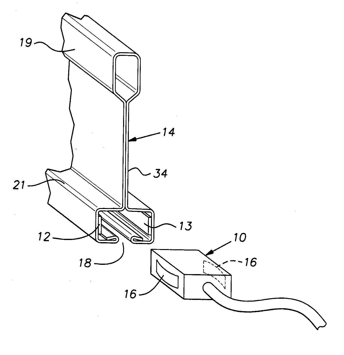
[0030]Referring now to FIG. 1, there is shown a connector 11 useful for electrically connecting a device to conductors 12, 13 carried on a generally conventional open slot grid tee 14. The device can be an AC to DC converter, typically converting 60 cycle 110-230 volts AC to 3 to 24 volts DC as desired. The electrical conductors 12, 13, typically, will be conductive strips of ink containing metal or carbon, metal foil, or metal tape. In other arrangements, the conductors 12, 13 can be metal wire such as copper or aluminum. In all instances, except where the grid tee 14 is an electrical insulator itself, the conductors will be electrically isolated from the grid tee by a suitable layer of electr...


PUM


Abstract

A suspended ceiling grid tee of conventional cross-sectional shape having a plurality of generally planar parallel and orthogonal surfaces and at least two electrically isolated conductor strips attached to the planar areas of the tee surfaces extending along substantially the full length of the tee, a connector for supplying low voltage electrical power to or from the conductors, the connector having a configuration complementary to the cross-sectional shape of the grid tee and including at least two electrical contacts for energizing each of said conductor strips when said connector is positioned on said grid tee.

Description

[0001]This application claims the priority of U.S. Provisional Application No. 61 / 118,067, filed Nov. 26, 2008.BACKGROUND OF THE INVENTION[0002]The invention relates to suspended ceiling structures and, in particular, to electrification of such ceiling structures.PRIOR ART[0003]Commercial building spaces such as offices, laboratories, light manufacturing facilities, health facilities, meeting and banquet hall facilities, educational facilities, common areas in hotels, apartments, retirement homes, retail stores, restaurants and the like are commonly constructed with suspended ceilings. These suspended ceiling installations are ubiquitous, owing to their many recognized benefits. Such ceilings ordinarily comprise a rectangular open grid suspended by wire from a superstructure and tile or panels carried by the grid and enclosing the open spaces between the grid elements. The most common form of grid elements has an inverted T-shaped cross-section. The T-shape often includes a hollow b...

Claims


Application Information

Patent Timeline
IPC IPC(8): H01R13/66E04C2/30
CPCE04B9/068E04B9/10H01R25/147E04B9/244H01R25/145E04B9/127E04B9/06E04B9/14
Inventor BOSS, DANIELLALONDE, PAUL D.GULBRANDSEN, PEDER
Owner USG INTERIORS LLC
Why Eureka
Try Eureka