
Ball seat assembly and method of controlling fluid flow through a hollow body

Inactive Publication Date: 2010-06-03
SPECIALISED GASOLINEEUM SERVICES GROUP
View PDF7 Cites 113 Cited by
  • Summary
  • Abstract
  • Description
  • Claims
  • Application Information

AI Technical Summary

Benefits of technology

[0009]Providing a ball seat assembly where the ball seat is moveable to a retracted position, facilitating passage of the ball through the ball seat and thereby re-opening fluid flow through the body bore, in response to a reduction in the fluid pressure force acting on the ball seat, offers significant advantages over prior ball seat assemblies. This is because it is not necessary to expose the ball to high pressures in order to re-open flow through the body bore. This reduces the risk of damage both to downhole components and surrounding geological formations.
[0015]The control mechanism may comprise a restraint for restraining the ball seat against movement relative to the body bore. The restraint may be adapted to release the ball seat for movement relative to the body bore on exposure of the ball seat to a fluid pressure force at or above a determined level. It will be understood that this fluid pressure force will depend upon the pressure of fluid acting on the ball and the dimensions of the ball seat and the ball. The restraint may take the form of a shear pin and may be rated to shear at or above a fluid pressure force acting on the ball seat which is greater than a typical range of operating pressures experienced downhole. This may prevent premature release of the ball seat for movement relative to the body bore.
[0024]According to a second aspect of the present invention, there is provided a method of controlling fluid flow through a hollow body, the method comprising the steps of:mounting a ball seat within a bore of the body;locating the ball seat in an extended position in which the ball seat defines a restriction to passage of a ball along the body bore;bringing a ball into abutment with the ball seat, to restrict fluid flow through the body bore and thereby causing an increase in a fluid pressure force acting on the ball seat for a given fluid pressure; andsubsequently lowering the fluid pressure force acting on the ball seat, to facilitate movement of the ball seat from the extended position to a retracted position spaced axially along the body bore from the extended position, in which position the ball seat releases the ball and permits passage of the ball along the body bore to thereby re-open fluid flow along the body bore.
[0028]The method may comprise raising a fluid pressure force acting on the ball after the ball has been brought into abutment with the ball seat, to carry out a further downhole procedure / operation, and / or to release a restraint (such as a shear pin) restraining movement of the ball seat relative to the body bore. This may be achieved by raising the pressure of fluid in the body bore above / upstream / uphole of the ball. Following carrying out of the downhole procedure and / or release of the restraint, the fluid pressure force acting on the ball may be lowered, by lowering the pressure of fluid in the body bore above / upstream / uphole of the ball, to facilitate movement of the ball seat to the retracted position.
[0029]According to a fourth aspect of the present invention, there is provided a ball seat assembly comprising:a hollow body defining a body bore;a ball adapted to be passed down into the body bore in a first axial direction; anda ball seat mounted within the body bore, the ball seat adapted to receive the ball and being selectively movable relative to the body bore in a second axial direction opposite to said first axial direction between an extended position in which the ball seat defines a restriction to passage of the ball along the body bore, and a retracted position in which passage of the ball along the body bore is permitted.
[0030]According to a fifth aspect of the present invention, there is provided a method of controlling fluid flow through a hollow body, the method comprising the steps of:mounting a ball seat within a bore of the body;locating the ball seat in an extended position in which the ball seat defines a restriction to passage of a ball along the body bore;passing a ball into the body bore in a first axial direction and bringing the ball into abutment with the ball seat, to restrict fluid flow through the body bore;moving the ball seat in a second axial direction opposite to said first direction from the extended position to a retracted position in which the ball seat releases the ball and permits passage of the ball along the body bore to thereby re-open fluid flow along the body bore.

Problems solved by technology

At these high pressures, when the ball shears the seat out, there is an undesirable hydraulic shock imparted to the workstring carrying the liner / setting tool, and indeed to the surrounding rock formations, which can cause serious damage.
Similar such problems are encountered where other downhole tools are provided with ball seats that shear out at such high pressures, and indeed other types of ball seats and balls which operate at high pressures.

Method used


Image

  • Ball seat assembly and method of controlling fluid flow through a hollow body
  • Ball seat assembly and method of controlling fluid flow through a hollow body
  • Ball seat assembly and method of controlling fluid flow through a hollow body

Examples


Embodiment Construction

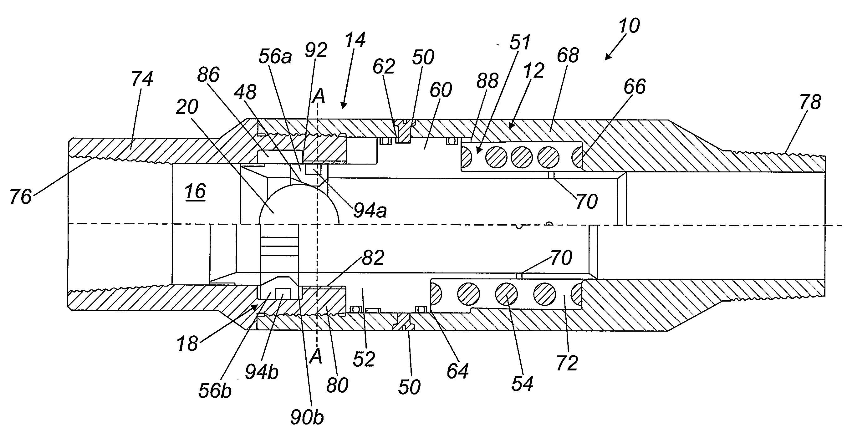
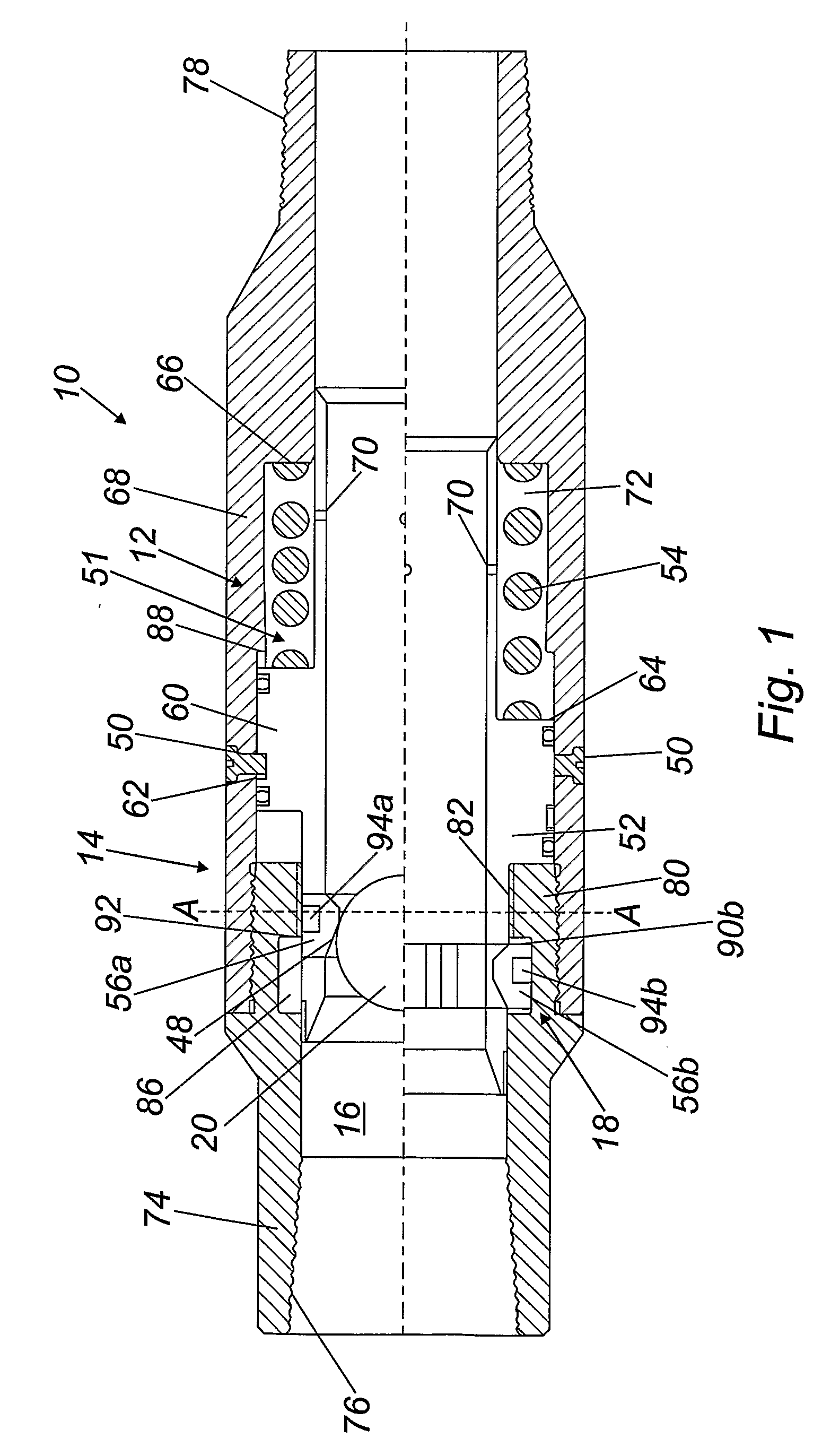
[0039]Turning firstly to FIG. 1, there is shown a downhole tool 10, incorporating a ball seat assembly indicated generally by reference numeral 12, in accordance with an embodiment of the present invention. As will be described in more detail below, the downhole tool 10 takes the form of a setting tool for setting tubing downhole. The ball seat assembly 12 generally comprises a hollow body 14 defining a body bore 16 and a ball seat 18 mounted within the body bore 16. The ball seat 18 is moveable relative to the body bore 16 between an extended position in which the seat defines a restriction to passage of a ball 20 along the body bore 16, and a retracted position spaced axially along the body bore 16 from the extended position and in which position passage of the ball 20 along the body bore 16 is permitted. The ball seat 18 is shown in the extended position with the ball 20 landed on the seat 18 in the upper half of FIG. 1, and in the retracted position following release of the ball...


PUM


Abstract

A method of controlling fluid flow through a hollow body, uses a ball seat assembly (12) comprising a hollow body (14) defining a bore (16) and a ball seat (18) mounted said bore, the ball seat being moveable relative to the bore between an extended position in which the seat defines a restriction to passage of a ball (20) along the bore, and a retracted position spaced axially along the bore from the extended position and in which position passage of the ball along the bore is permitted. A subsequent reduction in the fluid pressure force acting on the ball seat facilitates movement of the seat from the extended position shown in the upper half of FIG. 1, to the retracted position shown in the lower half of the Figure, to permit passage of the ball through the bore to thereby re-open fluid flow through the bore.

Description

TECHNICAL FIELD OF THE INVENTION[0001]The present invention relates to a ball seat assembly and to a method of controlling fluid flow through a hollow body. In particular, but not exclusively, the present invention relates to a ball seat assembly having a ball seat which selectively defines a restriction to passage of a ball along a bore of a hollow body, and to a method of controlling fluid flow through a hollow body using such a ball seat.BACKGROUND TO THE INVENTION[0002]In the oil and gas exploration and production industry; a wellbore or borehole of an oil or gas well is typically drilled from surface to a first depth and lined with a steel casing which is cemented in place. The borehole is then extended and a further section of smaller diameter casing is located in the extended section and also cemented in place. This process is repeated until the wellbore has been extended to a certain depth, and tubing known as a liner is then typically located in the borehole, extending from...

Claims


Application Information

Patent Timeline
IPC IPC(8): E21B34/06E21B34/00
CPCE21B23/006E21B34/14E21B23/04E21B23/02E21B34/142
Inventor TELFER, GEORGE
Owner SPECIALISED GASOLINEEUM SERVICES GROUP
Features
  • Generate Ideas
  • Intellectual Property
  • Life Sciences
  • Materials
  • Tech Scout
  • Unparalleled Data Quality
  • Higher Quality Content
  • 60% Fewer Hallucinations
Learn More