Aircraft engine mounting pylon comprising a tapered shim to secure the forward engine attachment

a technology for aircraft engines and pylons, which is applied in the direction of power plant arrangements/mountings, power plant construction, aircraft power plants, etc., can solve the problems of major mechanical stresses, non-negligible arrangement, and presence of a break on the lower spar, so as to improve the load transmission through the box structure, easy and less costly manufacturing, and satisfactory planarity characteristics

Inactive Publication Date: 2010-06-03
AIRBUS OPERATIONS (SAS)
View PDF15 Cites 38 Cited by
  • Summary
  • Abstract
  • Description
  • Claims
  • Application Information

AI Technical Summary

Benefits of technology

The invention allows for a rigid structure to be formed without a break in the lower spar at its forward end. This results in better load transmission and a planar spar that is easier and less costly to manufacture. The horizontal securing surface of the rigid structure consists entirely of a tapered shim with bearing points that offer excellent planarity characteristics. The horizontal securing surface extends entirely beneath the inclined lower spar without projecting laterally from it, which avoids increasing the width of the forward end of the box structure and minimizes aerodynamic disturbance. The rigid structure also includes a forward closing rib that ensures excellent passing of loads into the box, as they are directly injected into it.

Problems solved by technology

The technical problem addressed in this patent text is the need to improve the load transmission and engine mounting system of a pylon used to connect an engine and aircraft wing, while also minimizing the impact on the lower spar of the pylon.

Method used


Image

  • Aircraft engine mounting pylon comprising a tapered shim to secure the forward engine attachment
  • Aircraft engine mounting pylon comprising a tapered shim to secure the forward engine attachment
  • Aircraft engine mounting pylon comprising a tapered shim to secure the forward engine attachment

Examples


Embodiment Construction

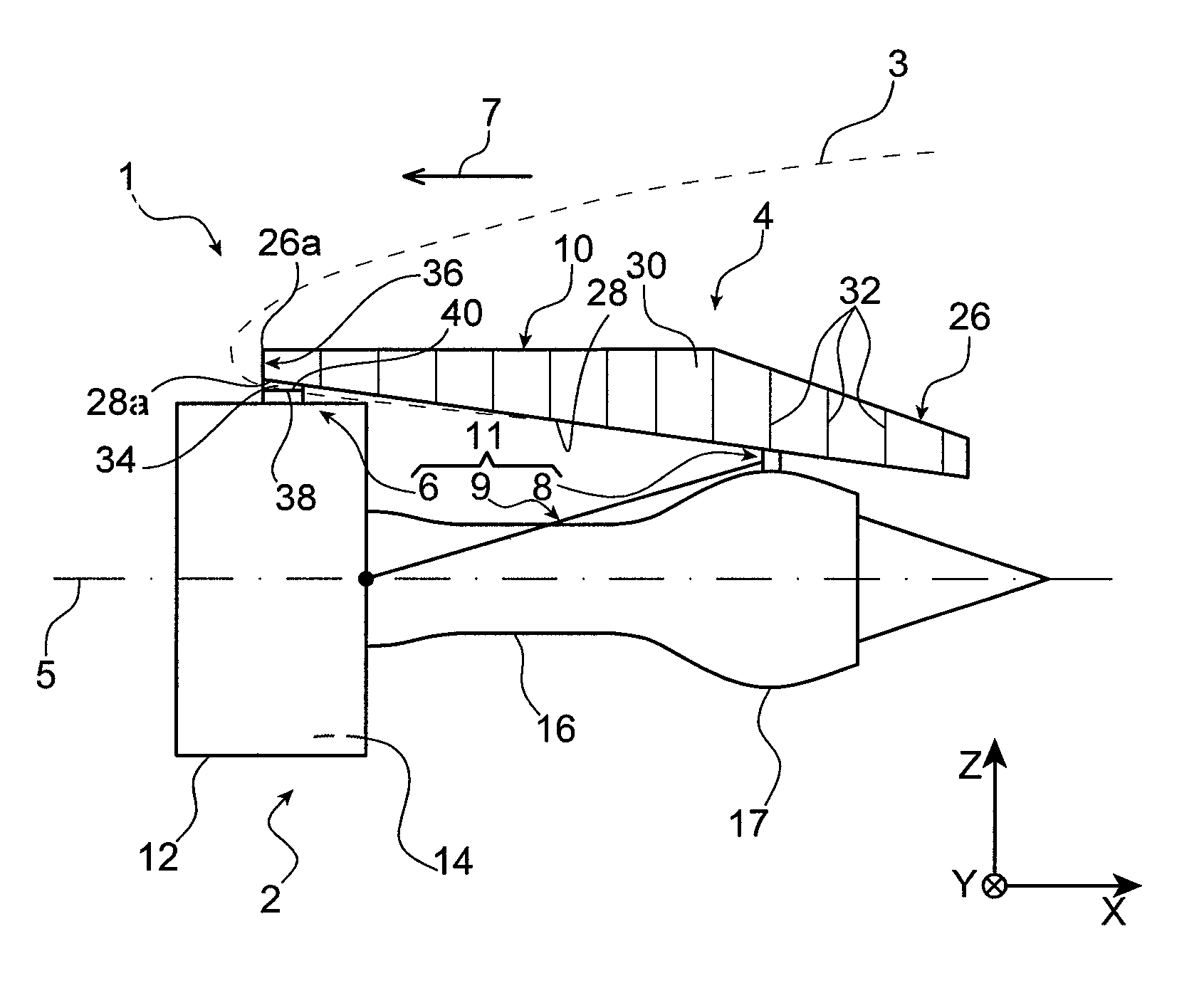
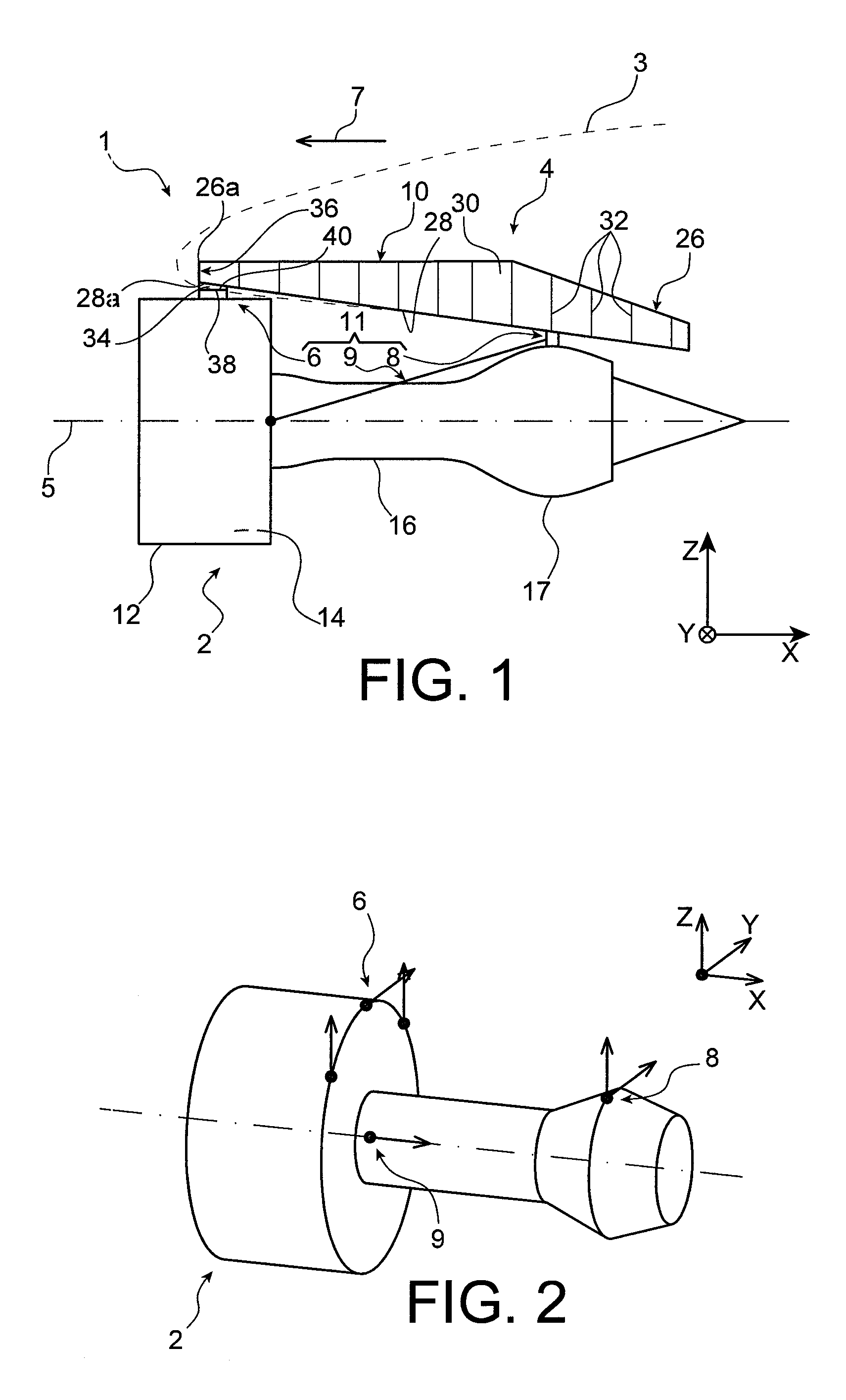
[0043]With reference to FIG. 1, an aircraft engine assembly 1 can be seen, intended to be attached below a wing 3 of this aircraft, this assembly 1 subject of the present invention being provided with a pylon 4 in the form of a preferred embodiment of the present invention.

[0044]Globally, the engine assembly 1 comprises an engine such as a turbojet engine 2 and the pylon 4, this pylon notably being provided with a rigid structure 10 and with an engine mounting system 11 consisting of a plurality of engine attachments 6, 8 and of a thrust load transmission device 9 to transmit the loads generated by the turbojet engine 2, the mounting system 11 therefore being positioned between the engine and the above-mentioned rigid structure 10. By way of indication, it is noted that the assembly 1 is intended to be surrounded by a nacelle (not shown in this figure) and that the pylon 4 comprises another series of attachments (not shown) used to mount this assembly 1 below the aircraft wing.

[0045...


PUM


Abstract

A mounting pylon for an aircraft engine. The pylon includes a rigid structure forming a box including an inclined lower spar and an upper spar, and an engine mounting system mounted fixedly on the structure and including a forward attachment including an attachment body including a horizontal securing surface lying flat against a horizontal securing surface of the rigid structure. The horizontal securing surface of the rigid structure is defined by a tapered shim mounted on the inclined lower spar, externally relative to the box.

Description


Claims


Application Information

Patent Timeline
Owner AIRBUS OPERATIONS (SAS)
Why Eureka
Try Eureka