
Material classifier having a scoop wheel

a technology of material classifier and scoop wheel, which is applied in the direction of solid separation, screening, sieving, etc., can solve the problems of high cost of maintenance and setup, high cost of scrap classifier, so as to achieve easy transportation and reduce production costs. , the effect of easy and less cost of manufactur

Inactive Publication Date: 2008-04-15
THOR GLOBAL ENTERPRISES
View PDF26 Cites 2 Cited by
  • Summary
  • Abstract
  • Description
  • Claims
  • Application Information

AI Technical Summary

Benefits of technology

"The present invention provides an improved material classifier that is cost-effective, reliable, and easy to manufacture and transport. The scoop wheel rotates at an angle relative to the horizontal, and multiple scoops can be used in series or independently to perform the functions of cleaning, separation, and dewatering. The scoop wheel can be easily offset from the stream of material being classified. The classification system can be used for sand and other materials, and can be increased in capacity or throughput by adding additional scoops or using a second scoop wheel. The method involves scooping material from a tank and discharging it over an edge of the tank. The invention provides a more efficient and effective material classifier for separating solid materials from liquids."

Problems solved by technology

Screw classifiers can be complex, prone to wear, and can be expensive and costly to maintain and set up.
A common drawback of existing classifier designs is that good classifying ability is typically achieved at the expense of capacity and vice versa.
Typically, a material classifier has either good classifying ability but low capacity and a complicated reclaiming system, or high capacity and a relatively simple reclaiming system but poor classifying ability.
A further drawback of most material classifiers is that they are large and not easily portable between job sites.
Some material classifiers, such as those at a quarry or aggregate pit, are typically large installations requiring a support structure and therefore cannot be transported.
In addition to being a source of downtime, loading and unloading of the classifier requires equipment at both the initial and final destinations to perform the loading / unloading operation.
Further, these types of classifiers may require some disassembly for transportation and reassembly on arrival.

Method used


Image

  • Material classifier having a scoop wheel
  • Material classifier having a scoop wheel
  • Material classifier having a scoop wheel

Examples


Embodiment Construction

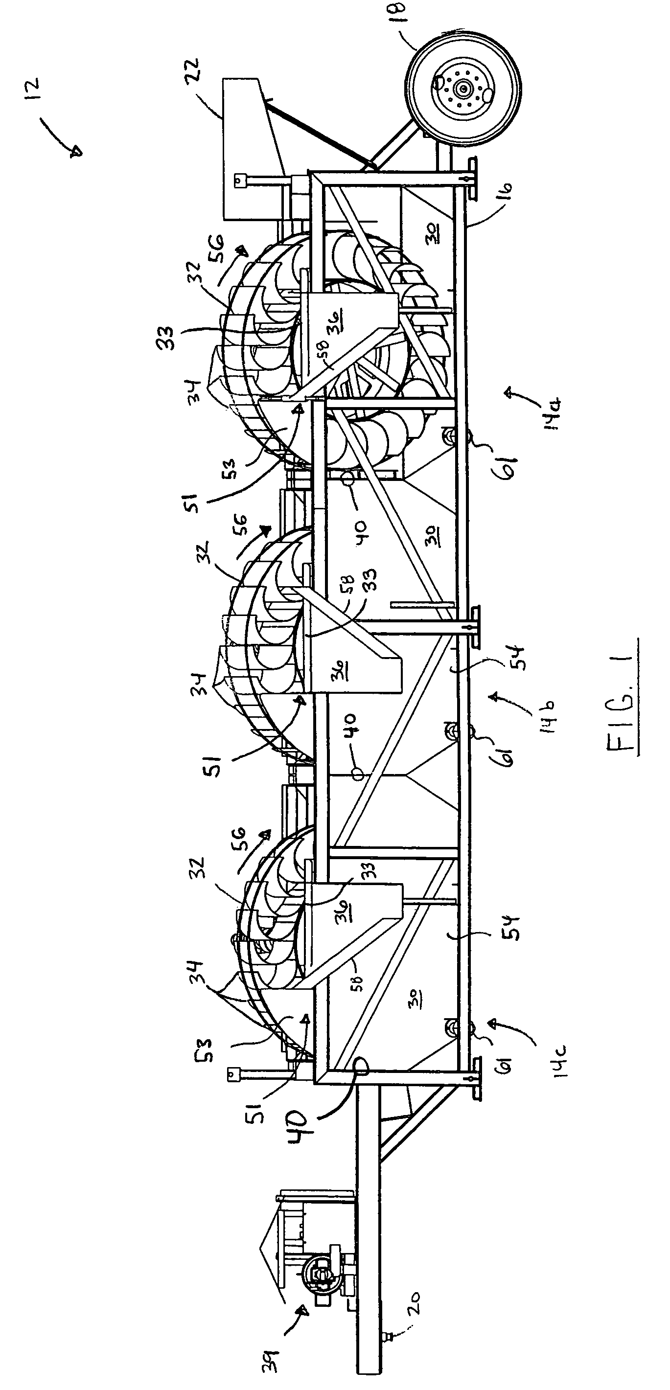
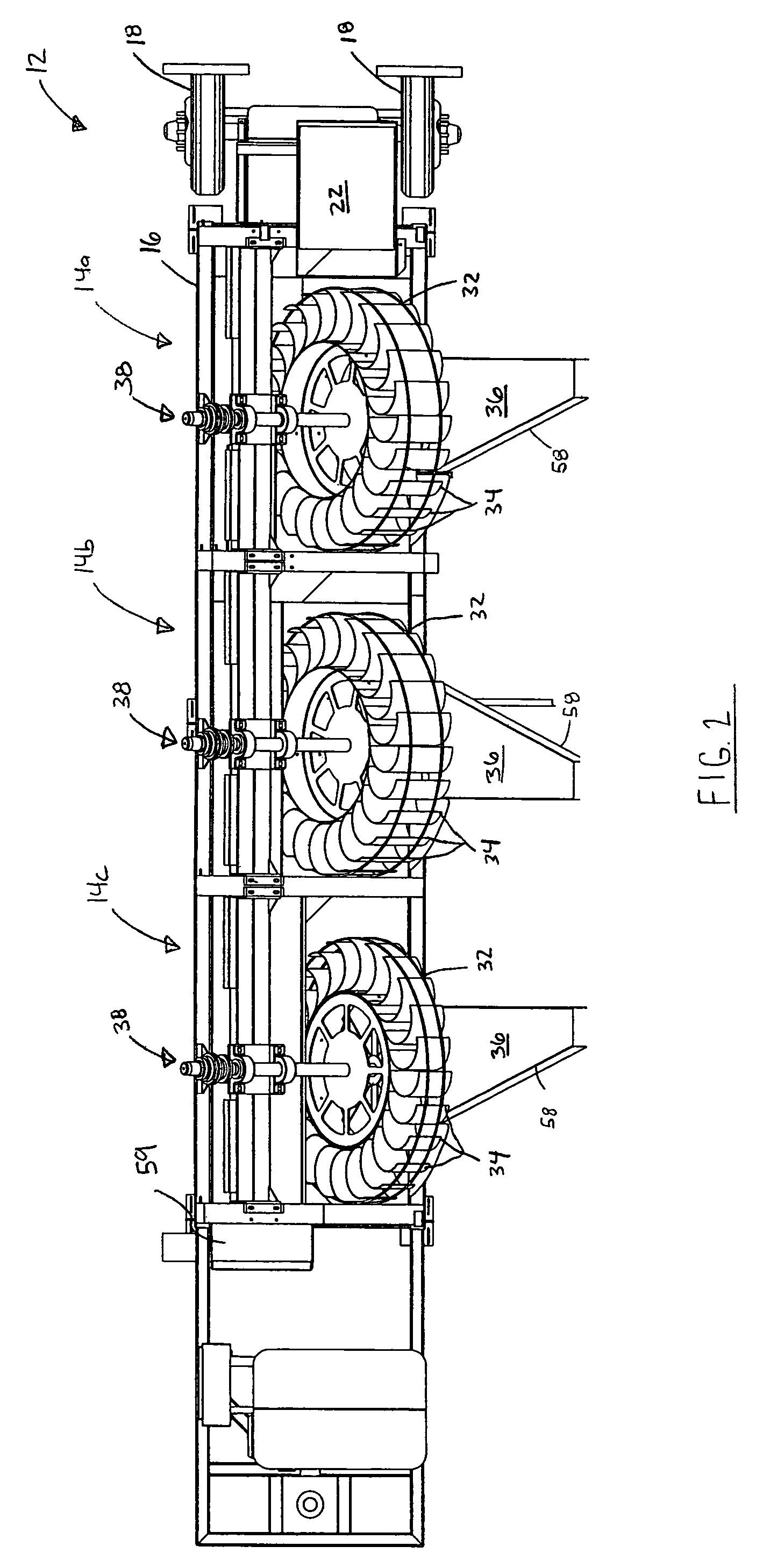
[0045]Reference is first made to FIG. 1 to 4, which show a system 12 for classifying a liquid-solid mixture implemented according to the present invention. The system 12 comprises material classifiers 14, indicated individually by references 14a, 14b and 14c, a support frame 16, wheels 18, hitch 20, and a mixing box 22. The material classifiers 14 are coupled in succession to form a series of three classifier stages beginning with the first material classifier 14a. In other embodiments, greater or fewer stages may be used. A single material classifier 14 may be used, if desired.

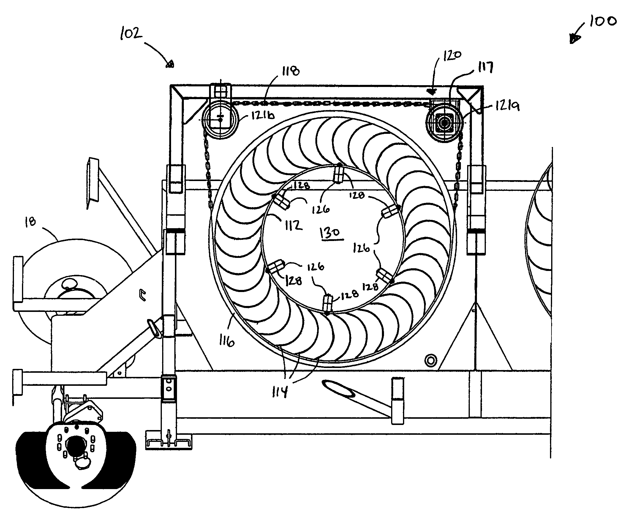
[0046]Each material classifier 14 comprises a tank or hopper 30, and an angularly mounted scoop wheel 32 having a plurality of radially extending, curved scoops or lifts 34. The wheels 32 and their corresponding scoops 34 scoop settled material out of the tanks 30 and deposit it on discharge ramps or chutes 36. Each discharge chute 36 directs the scooped material onto a corresponding conveyor belt 37 (FIG. 6)...


PUM


Abstract

A material classifier for classifying a liquid-solid mixture containing solid material to be separated is provided. The material classifier includes a tank defining a reservoir for receiving the liquid-solid mixture, and a scoop wheel including a plurality of circumferentially spaced apart scoops for scooping material from the tank and subsequently discharging the scooped material from the tank during rotation of the scoop wheel. A classification system and method of classifying material is also provided.

Description

RELATED APPLICATION INFORMATION[0001]This application claims priority from Canadian patent application Ser. No. 2,448,857, filed Nov. 10, 2003, and U.S. provisional patent application Ser. No. 60 / 572,602, filed May 20, 2004.FIELD OF THE INVENTION[0002]The present invention relates to material classifiers, material washers and dewatering devices, and more particularly to material classifiers having a scoop wheel.BACKGROUND OF THE INVENTION[0003]Material classifiers are used for many different purposes, including the separation or classification of solids according to size and / or particle density. Many different types of material classifiers are known, including mechanical and non-mechanical types.[0004]According to one type of material classifier, solids to be separated are mixed in a suitable liquid such as water, to create a liquid-solid mixture or pulp. The mixture is then introduced into a classifier tank. Larger particles settle to the bottom of the classifier tank while fine pa...

Claims


Application Information

Patent Timeline
Patent Type & Authority Patents(United States)
IPC IPC(8): B03B5/60B03B7/00B03B1/00B03B5/42B07B1/00
CPCB03B5/42B03B2011/004
Inventor JOHANNSEN, THOR J.
Owner THOR GLOBAL ENTERPRISES
Learn More