
Methods and devices for acoustophoretic operations in polymer chips

a polymer chip and acoustophoretic technology, applied in the field of acoustophoretics, can solve the problems of low acoustophoretic efficiency, low separation efficiency, and low efficiency of acoustophoretic operations, and achieve the effects of reducing production costs, reducing labor intensity, and efficient use of polymeric substrates

Active Publication Date: 2022-05-17
ACOUSORT
View PDF3 Cites 0 Cited by
  • Summary
  • Abstract
  • Description
  • Claims
  • Application Information

AI Technical Summary

Benefits of technology

The present invention provides a way to use cheaper and more easily manufacturable polymeric substrates for ultrasound transducers. This also makes it easier to integrate with other operations in polymeric cartridges. The method also matches the inherent resonance frequency of the ultrasound transducer with the frequency f to maximize efficiency.

Problems solved by technology

These attempts have however achieved only limited success as the acoustophoretic efficiency, including throughput and separation efficiency, has been low.
Also surface acoustic waves (SAW) can be used to induce acoustophoresis in a channels defined at least in part by polymer walls, but these systems are also very limited in separation efficiency and / or troughput.

Method used


Image

  • Methods and devices for acoustophoretic operations in polymer chips
  • Methods and devices for acoustophoretic operations in polymer chips
  • Methods and devices for acoustophoretic operations in polymer chips

Examples


example 1b

Simulation Comparing Asymmetric and Symmetric Actuation

Materials and Method

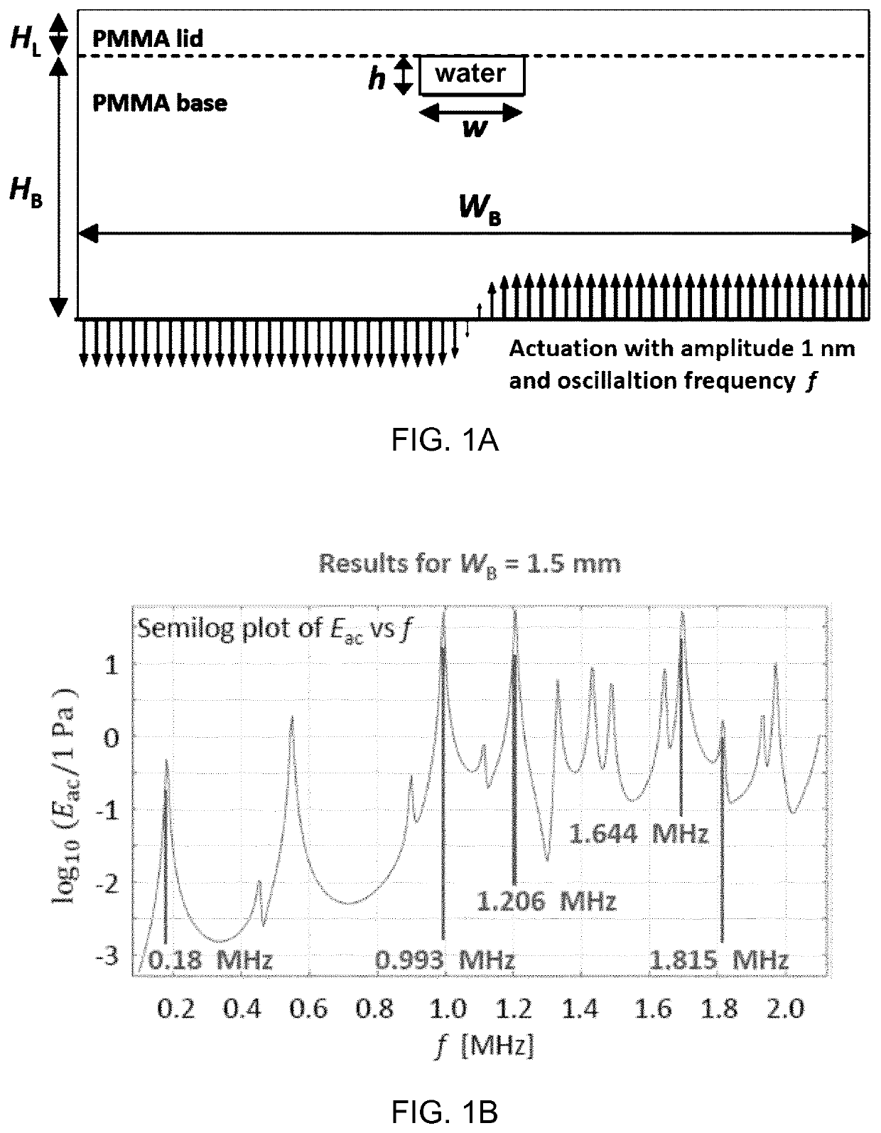
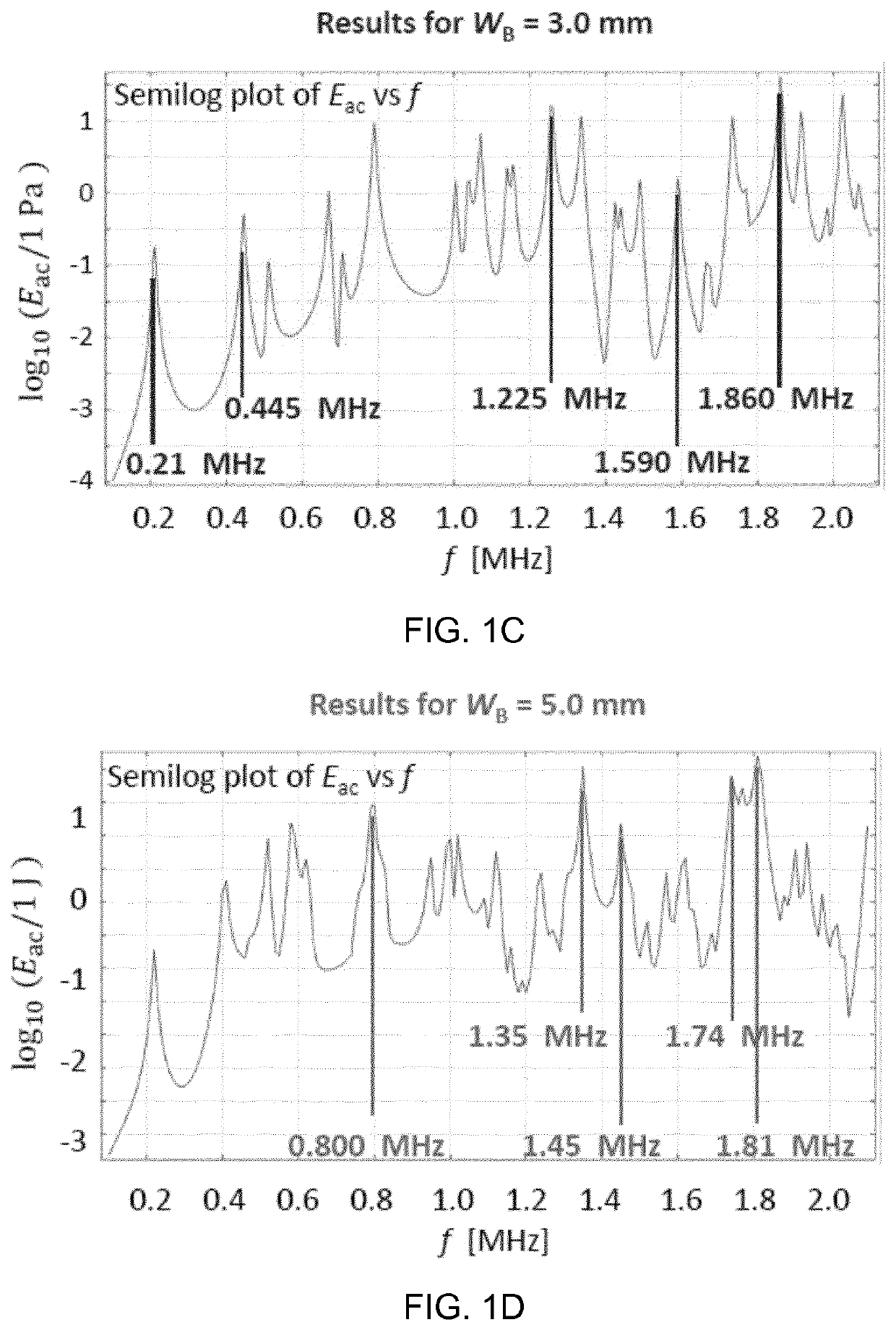
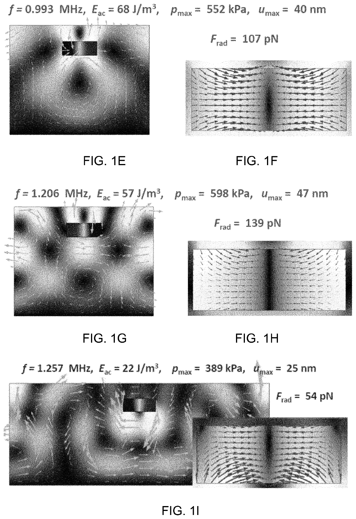
[0131]As in example 1 for WS=3.0 mm and a total height of the chip=1.18 mm. The frequency f=1.745 MHz was selected and simulations were performed for an asymmetric actuation and symmetric actuation.

Results

[0132]FIG. 1M shows Frad for symmetric actuation at 1.380 MHz. The force vectors are directed towards the side walls of the channel.

[0133]FIG. 1N shows Frad for symmetric actuation at 1.745 MHz. The force vectors are directed towards the ceiling of the channel and also towards the side walls of the channel.

example 2

3D Simulation of Part of PMMA Chip

Materials and Method

[0134]A PMMA chip 1B, see example 4 for dimensions was simulated using the parameters of example 2. The simulation was made using the ¼-symmetry:

0x<Ls / 2Ls=40 mm

0y<Ws / 2Ws=3 mm

0z<Hs Hs=1.18 mm

[0135]The asymmetric actuation, defined as (0.1 nm)*tan h(50*y / Ws) was applied in the xy plane at z=0.

[0136]The xy plane at y=0 has antisymmetric boundary conditions due to actuation and the yz-plane at x=0 has symmetrical boundary conditions due to the symmetry away from the center plane in the chip along the x-axis.

Results

[0137]The two largest resonances, as measured using the acoustic energy Eac was found for 1.29 MHz, which corresponds exactly to the experimental value, see example 4, and 1.63 MHz which is about 105% of the experimental value of 1.55 MHz, see FIG. 2A.

[0138]For 1.29 MHz the maximum Frad was 4.0 pN (note here that the amplitude of the actuation is 1 / 10 of the amplitude used in example 1, hence the lower Frad. FIG. 2...

example 3

3D Simulation of Full Chip

Materials and Method

[0140]Chips 1B (WS=3.0 mm) and 1F (WS=5.0 mm), both having the height (HS=1.18 mm) and length (LS=50 mm) over the full height using the quarter vertical transverse symmetry plane and the vertical axial anti-symmetry to reduce the geometry to a quarter (0S / 2=25 mm and 0S / 2=1.5 mm or 2.5 mm) as in example 2.

Results

[0141]The table below compares the resonance frequencies predicted by the simulation with those identified in the experiments, see example 4.

[0142]Chip 1B

[0143]

f (MHz) / f (MHz) / f (MHz) / f (MHz) / ResonanceFrad (pN)Frad (pN)Frad (pN)Frad (pN)Simulation1.132 / 0.381.277 / 0.051.381 / 0.201.455 / 0.88Experiment1.29——1.550

[0144]FIG. 3A shows the acoustic energy Eac for chip 1B, and FIG. 3B shows Frad in the center of the channel for f=1.456 MHz.

[0145]Chip 1F

[0146]

f (MHz) / f (MHz) / f (MHz) / f (MHz) / f (MHz) / ResonanceFrad (pN)Frad (pN)Frad (pN)Frad (pN)Frad (pN)Simulation1.027 / 1.330 / 01.415 / 1.731 / 1.790 / 0.071.050.540.31Experiment1.1201.3301.4601.770—

[01...


PUM

PropertyMeasurementUnit
frequencyaaaaaaaaaa
frequencyaaaaaaaaaa
frequencyaaaaaaaaaa

Abstract

The invention relates to a method of performing an acoustophoretic operation, comprising the steps of: a. providing an acoustophoretic chip comprising a polymer substrate in which a microfluidic flow channel is positioned, b. providing at least one ultrasound transducer in acoustic contact with one surface of the substrate, c. actuating the at least one ultrasound transducer at a frequency f that corresponds to an acoustic resonance peak of the substrate including the microfluidic flow channel filled with a liquid suspension, and d. providing the liquid suspension in the flow channel to perform the acoustophoretic operation on the liquid suspension. The invention further relates to an acoustophoretic device, a method of producing an acoustophoretic device, and a microfluidic system comprising the acoustophoretic device.

Description

CROSS-REFERENCE TO RELATED APPLICATION[0001]This application is the National Phase, under 35 U.S.C. § 371(c), of International Application No. PCT / EP2018 / 073542, filed Aug. 31, 2018, which claims priority from European Application No. EP 17188920.7, filed Aug. 31, 2017. The disclosures of all of the referenced applications are incorporated herein by reference in their entirety.FEDERALLY SPONSORED RESEARCH OR DEVELOPMENT[0002]Not ApplicableTECHNICAL FIELD OF THE INVENTION[0003]The present invention relates generally to the field of acoustophoresis in which ultrasound is used to actuate waves in liquids and suspensions for interacting with different types of particles in said liquids and suspensions to perform inter alia separation and sorting of the particles. The present invention particularly relates to methods and devices for performing such acoustophoretic operations in polymer chips instead of the commonly used glass or silicon chips.BACKGROUND OF THE INVENTION[0004]Acoustophore...

Claims


Application Information

Patent Timeline
Patent Type & Authority Patents(United States)
IPC IPC(8): B01L3/00
CPCB01L3/50273B01L3/502707B01L3/502753B01L3/502761B01L2200/0652B01L2300/12B01L2400/0439B01L2300/0816B01L2300/0864
Inventor BRUUS, HENRIKMOISEYENKO, RAYISAFRELTOFT, TORSTENOHLSSON, PELLEJAKOBSSON, OLA
Owner ACOUSORT
Learn More