Light emitting device and a drive control method for driving a light emitting device

a technology of light emitting devices and control methods, which is applied in the direction of instruments, cathode-ray tube indicators, electric digital data processing, etc., can solve the problems of current amplification factor, affecting the mobility of irregularities, and the inability to avoid the origin of manufacturing processes

Active Publication Date: 2010-06-03
SOLAS OLED LTD
View PDF12 Cites 72 Cited by
  • Summary
  • Abstract
  • Description
  • Claims
  • Application Information

AI Technical Summary

Benefits of technology

[0061]The present invention provides a light emitting device and a device control method for driving a light emitting device, which can correct a voltage v

Problems solved by technology

Irregularity in the current amplification factor is due to irregularity in mobility.
However, even so, the affects of ir

Method used


Image

  • Light emitting device and a drive control method for driving a light emitting device
  • Light emitting device and a drive control method for driving a light emitting device
  • Light emitting device and a drive control method for driving a light emitting device

Examples


Embodiment Construction

[0081]A detailed description will be given hereafter regarding a pixel driving device, light emitting device, and property parameter acquisition method in a pixel driving device according to the present invention with reference to embodiments shown in drawings. In addition, the light emitting device is described as a display device in the present embodiments.

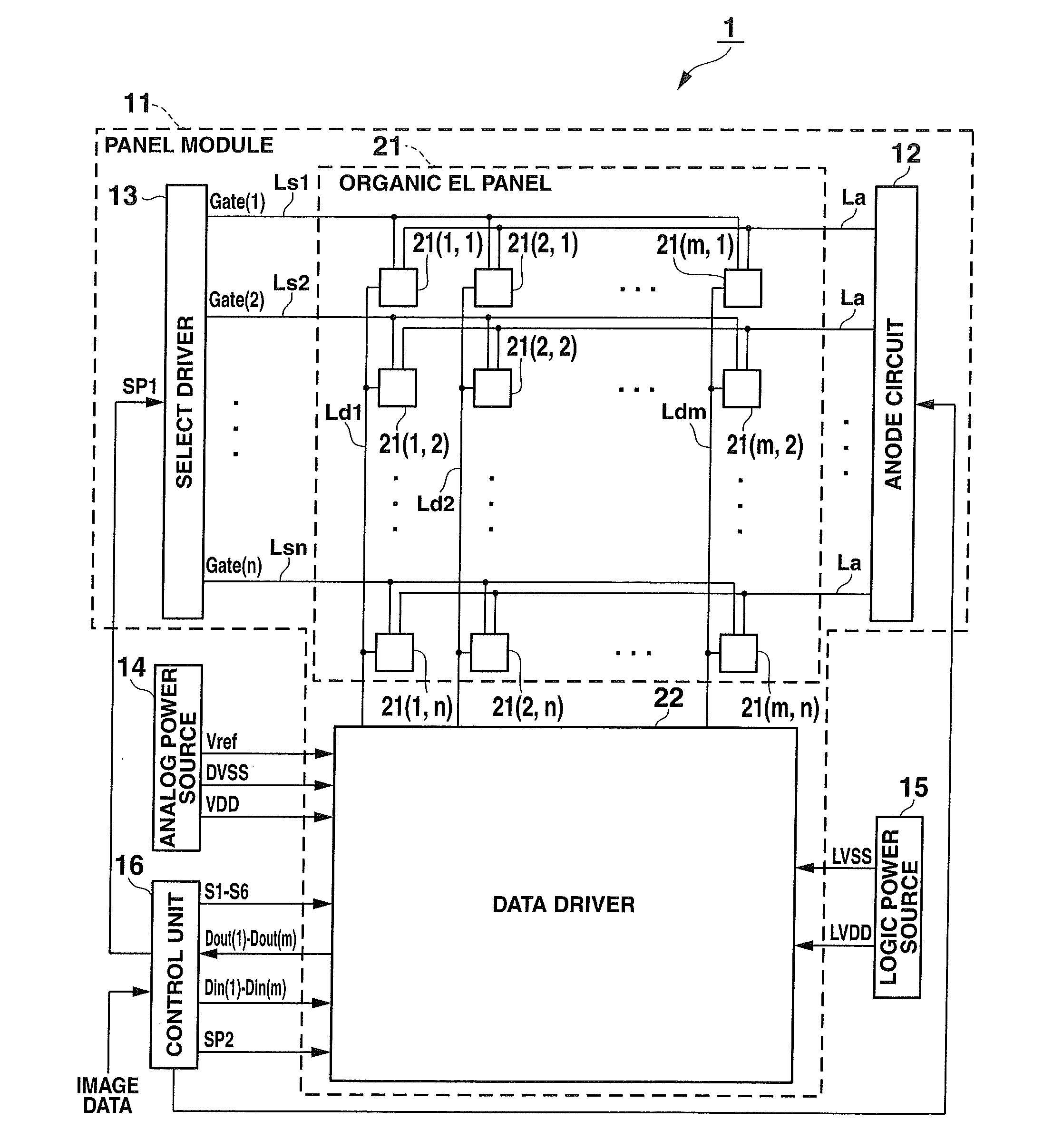
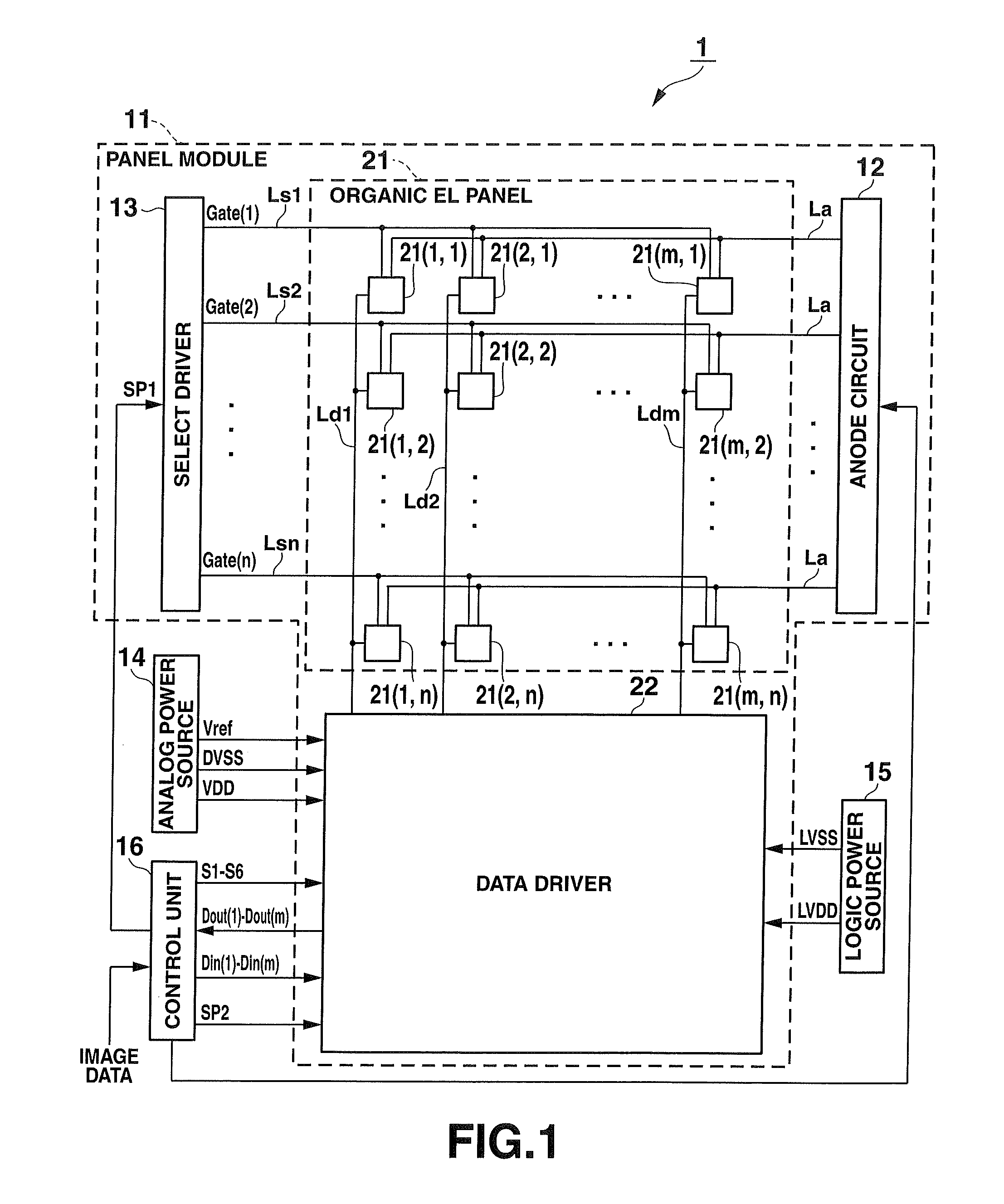
[0082]FIG. 1 shows a constitution of a display device according to the present embodiment. The display device (light emitting device) 1 according to the present embodiment is composed of a panel module 11, an analog power source (voltage impressing circuit) 14, a logic power source 15, and a control unit (including a parameter acquisition circuit and a signal correction circuit) 16.

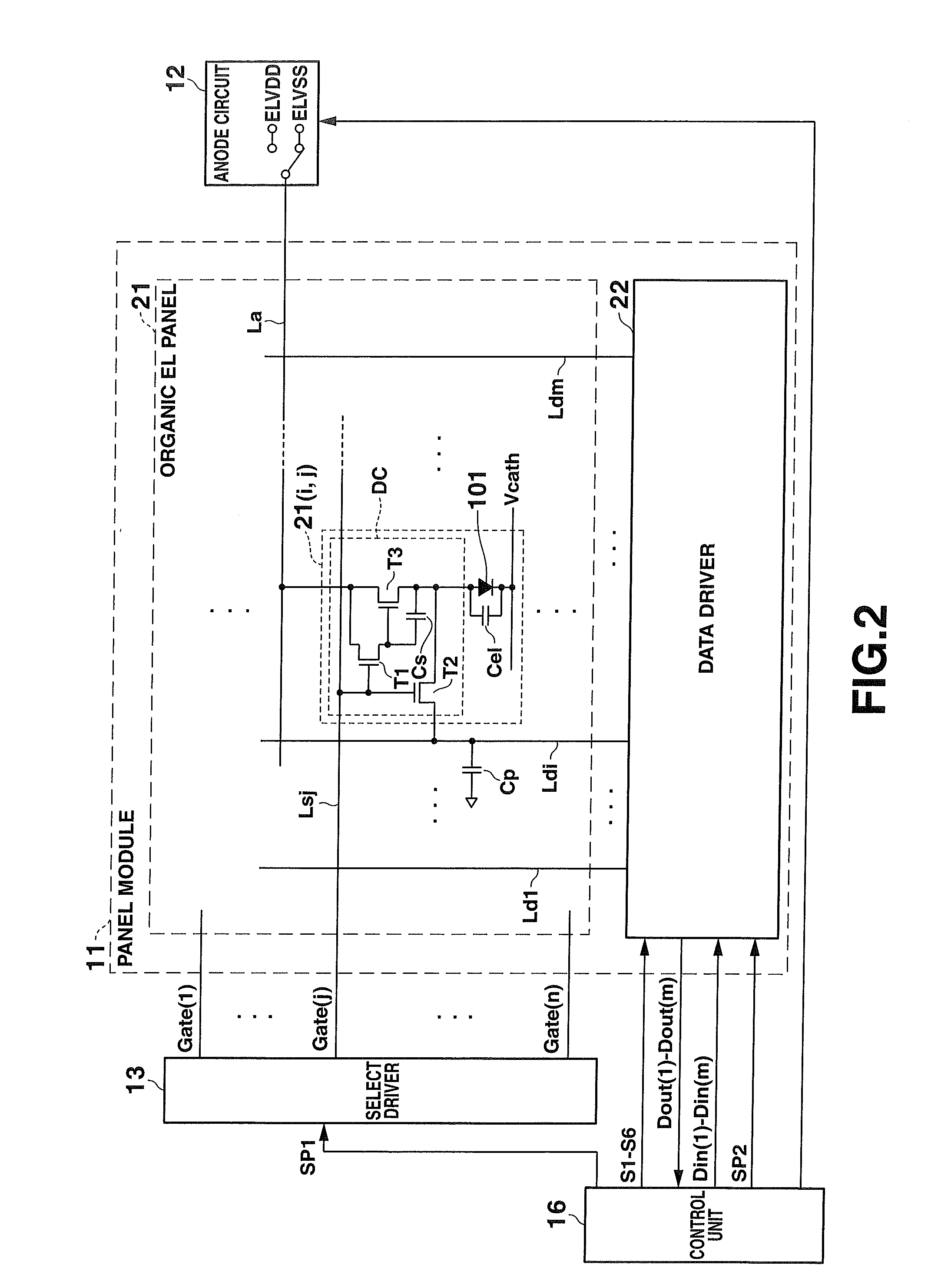
[0083]The panel module 11 provides an organic EL panel (pixel array) 21, a data driver (a signal line driving circuit) 22, an anode circuit (power driving circuit) 12, and a select driver (select driving circuit) 13.

[0084]The organic EL panel 21 provi...


PUM


Abstract

A light emitting device has a plurality of pixels, each of which includes a drive transistor, a light emitting element and signal lines, a property parameter acquisition circuit which acquires property parameter, a signal correction circuit that generates a corrected gradation signal by correcting the image data based on the property parameter, and a drive signal impressing circuit that impresses a drive signal, generated based on the corrected gradation signal, on the pixel to drive it. The property parameter is constituted of a threshold voltage, a current amplification factor and its irregularity of the drive transistor, and is acquired based on measured voltages of the signal lines after each of a plurality of predetermined settling times elapses from the time when the light emitting device cuts off a voltage subsequent to impressing the voltage on each pixel for a predetermined length of time.

Description

BACKGROUND OF THE INVENTION[0001]1. Field of the Invention[0002]The present invention relates to a light emitting device and a drive control method for driving a light emitting device.[0003]2. Description of the Related Art[0004]Research and development has been gaining in popularity in recent years around light emitting element type display devices (light emitting element type display, light emitting device) that provide a display panel (pixel array) arranging light emitting elements in a matrix as the next generation of display device to succeed liquid crystal display devices.[0005]Electric current driven type light emitting elements, such as organic electroluminescence elements (organic EL element) and inorganic electroluminescence elements (inorganic EL element), or a light emitting diode (LED), are known as this type of light emitting element.[0006]A light emitting element type display device that applies an active matrix drive method, compared to known liquid crystal display d...

Claims


Application Information

Patent Timeline
IPC IPC(8): G09G5/00
CPCG09G3/3233G09G2320/043G09G2300/0842G09G3/3291
Inventor OGURA, JUNTAKEI, MANABUKASHIYAMA, SHUNJI
Owner SOLAS OLED LTD
Why Eureka
Try Eureka