Alertness sensing spectacles

a technology of alertness and spectacles, applied in the field of alertness sensing spectacles, can solve the problems of many people being unaware of their drowsiness, the problem of affecting the ability of operators, and the inability to solve the problem of drowsiness driving, so as to reduce the proportion of signals

Active Publication Date: 2010-06-03
SDIP HLDG
View PDF4 Cites 52 Cited by
  • Summary
  • Abstract
  • Description
  • Claims
  • Application Information

AI Technical Summary

Benefits of technology

[0031]d) said sensor unit incorporating a light (preferably infra red) emitter and a light (preferably infra red) detector recessed into the s...

Problems solved by technology

The detection of drowsiness is of importance because drowsiness impairs the ability of operators of a wide range of equipment including motor vehicles, aircraft and boats as well as industrial equipment.
The problem of drowsy driving cannot be solved by educating drivers to take remedial action when feeling drowsy.
The difficulty is tha...

Method used


Image

  • Alertness sensing spectacles
  • Alertness sensing spectacles
  • Alertness sensing spectacles

Examples


first embodiment

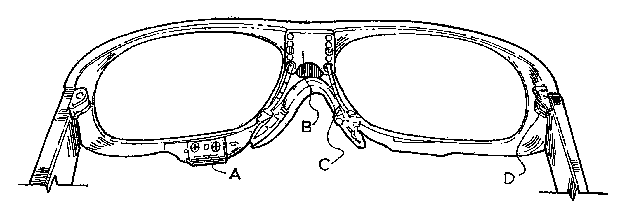
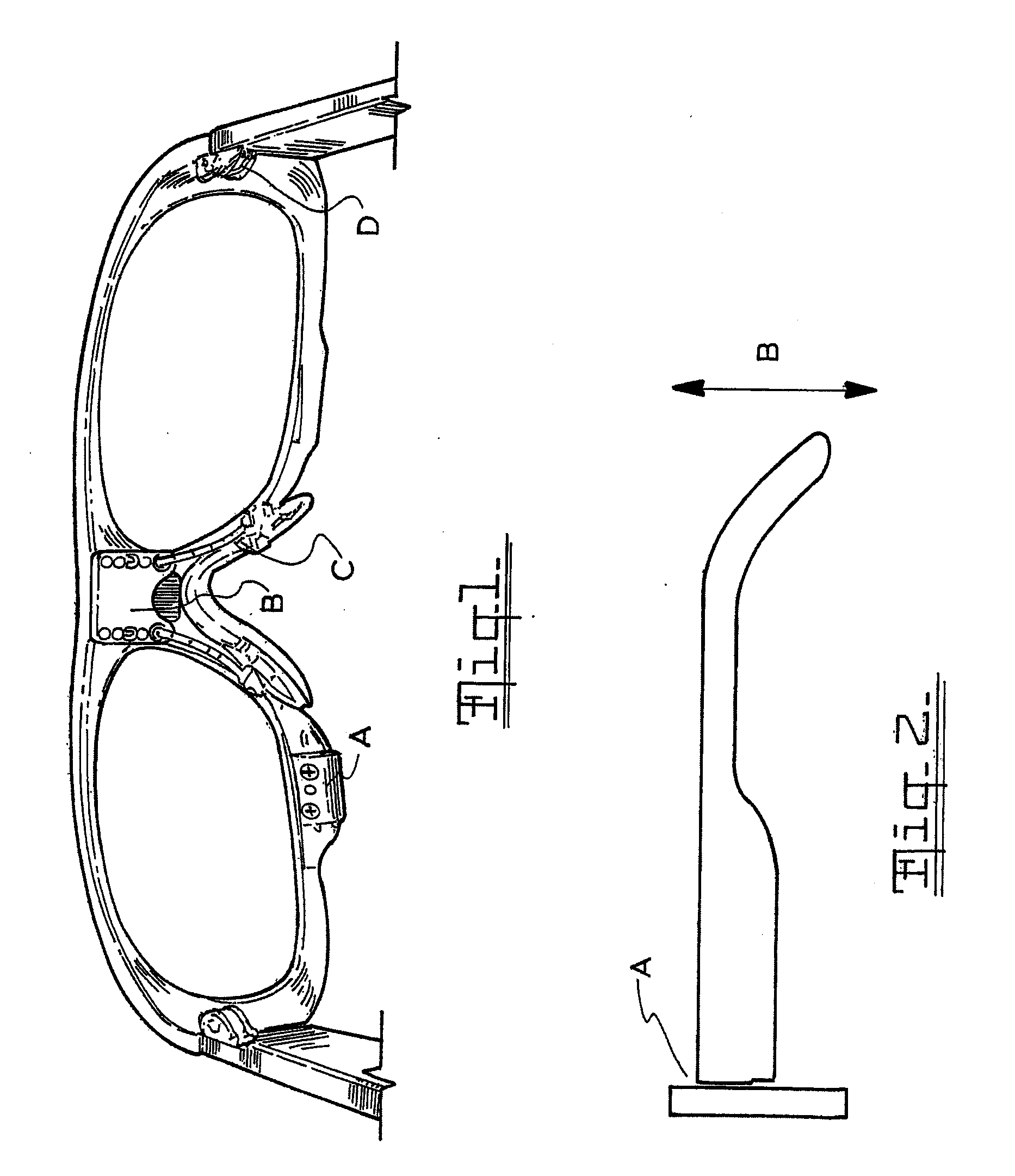
[0034]FIG. 1 is a rear view of the spectacles according to the invention;

[0035]FIG. 2 is a schematic view of the connection between the ocular frame and the frame arm;

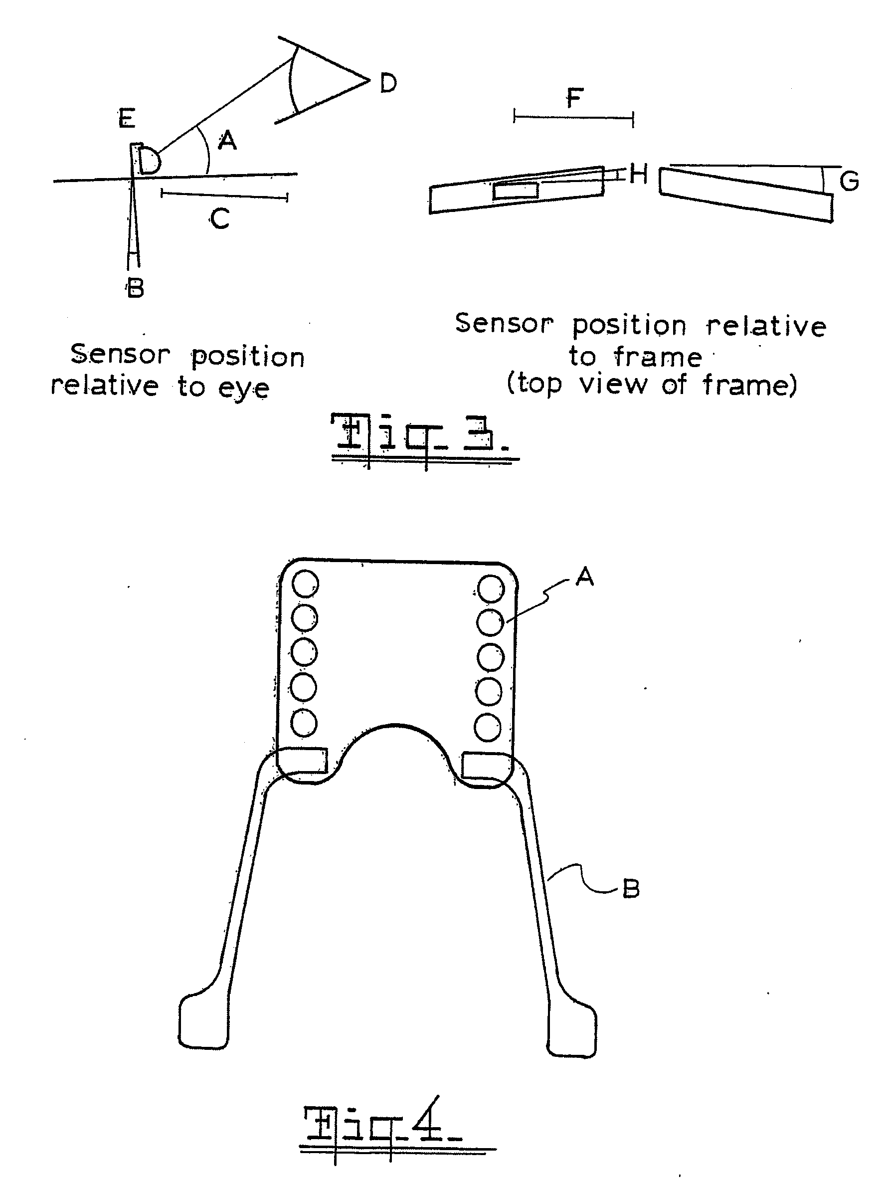
[0036]FIG. 3 illustrates the relationship between the position of sensor unit and the eye;

[0037]FIG. 4 illustrates one embodiment of the nose bridge of this invention;

[0038]FIG. 5 shows the nose bridge relative to the ocular frames;

[0039]FIG. 6 schematically illustrates the arrangement of the sensor unit;

second embodiment

[0040]FIG. 7 is an exploded view of the frame of this invention in a second embodiment;

[0041]FIG. 8 is detailed view of FIG. 7;

[0042]FIG. 9 illustrates the interchangeability of the ocular lenses;

[0043]FIG. 10 illustrates the pivoting of the ocular lenses in the embodiment shown in FIG. 7;

[0044]FIG. 11 is a rear view of the frame of FIG. 7 illustrating the attachment of the sensor arm;

[0045]FIG. 12 is a detail illustrating the sensor arm adjustment mechanism;

[0046]FIG. 13 illustrates the sensor pad unit with cable used in the embodiment of FIG. 7;

[0047]FIG. 14 is a detailed view of the sensor pad;

[0048]FIG. 15 is a view of the sensor pod incorporating the sensor pad of FIG. 14;

[0049]FIG. 16 illustrates location of the embodiment of FIG. 7 relative to the nose and eyes of a wearer;

[0050]FIGS. 17A B and C illustrate 3 views of the frame of this invention incorporating a nose adjustment piece;

[0051]FIGS. 18A and B illustrates 2 views of the frame of this invention with a second nose ad...


PUM


Abstract

Spectacles for use in an eye monitoring system include a pair of ocular frames and a sensor unit adapted to be positioned adjacent an eye of the wearer. A nose bridge connects the ocular frames and incorporates an adjustment mechanism for adjusting the vertical position of the sensor unit relative to the eye. A frame arm extends from the outer edge of each ocular frame and is adapted to fit over the ear of a wearer. The sensor unit incorporates two infra red emitters at different angles and an infra red detector recessed into the surface of the unit to reduce the proportion of signal received by said detector which is not from the signal emitter reflected by the eye or eyelids.

Description

[0001]This invention relates to spectacles used in monitoring eye and eyelid movement.BACKGROUND TO THE INVENTION [0002]The detection of drowsiness is of importance because drowsiness impairs the ability of operators of a wide range of equipment including motor vehicles, aircraft and boats as well as industrial equipment. The problem of drowsy driving cannot be solved by educating drivers to take remedial action when feeling drowsy. The difficulty is that many people are unaware of their drowsiness before and during the drowsiness even though they may be alert and aware after they rouse. This means one cannot predict when their level of drowsiness will next decrease to the point of danger because the drowsy state involves a loss of awareness of the present; an involuntary lapse of attention.[0003]U.S. Pat. No. 5,745,038 discloses an eye monitor that examines reflected light from the eye to detect blinking behavior as an indicator of drowsiness.[0004]U.S. Pat. No. 6,097,295 discloses...

Claims


Application Information

Patent Timeline
IPC IPC(8): A61B3/113
CPCA61B5/18G08B21/06A61B5/6814A61B5/163G08B21/00G02C11/00
Inventor JOHNS, MURRAYBROWN, AARON
Owner SDIP HLDG
Why Eureka
Try Eureka