This helps you quickly interpret patents by identifying the three key elements:
Problems solved by technology
Method used
Benefits of technology
Benefits of technology
[0012]In view of the above problem in the lamp unit which comprises the reflector having the reflection member and the plurality of bar-shaped light source lamps each inserted into the reflector, it is an object of the present invention to optimize a positional relationship between the reflection member and each of the bar-shaped light source lamps so as to obtain enhanced illumination efficiency.
[0013]Through various researches for achieving the above object, the inventor of this application found that respective protrusion lengths of the reflection member and each of the bar-shaped light source lamps have a significant influence on illumination efficiency of the lamp unit. The inventor also found that the illumination efficiency is enhanced when the protrusion length of the reflection member is set in the range of one-third to three-fourths of the protrusion length of each of the bar-shaped light source lamps. Based on this knowledge, the inventor has accomplished the present invention.
[0015]In the lamp unit of the present invention, illumination efficiency can be enhanced by allowing the protrusion length of the reflection member to be set in the range of one-third to three-fourths of the protrusion length of the insertion portion of each of the bar-shaped light source lamps. If the protrusion length of the reflection member is set to be less than one-third of the protrusion length of the insertion portion of the bar-shaped light source lamp, the illumination efficiency will deteriorate. Contrariwise, if the protrusion length of the reflection member is set to be greater than three-fourths of the protrusion length of the insertion portion of the bar-shaped light source lamp, a presence of the reflection member is liable to adversely hinder light reflection in the reflector to cause the occurrence of a shadow on an illumination target, such as a floor.
[0017]In the lamp unit of the present invention, when the insertion portion of each of the bar-shaped light source lamps is formed to have a prismatic-shaped outer peripheral surface, any one or more facets of the prismatic-shaped outer peripheral surface located opposed to a certain region of the reflective surface of the reflection member are preferably positioned in non-parallel relation to the region of the reflective surface of the reflection member. According to this feature, light from each of the bar-shaped light source lamps will be reflected in a direction different from a direction oriented toward the insertion portion of the bar-shaped light source lamp. Thus, the reflected light can be effectively utilized for illumination to obtain further enhanced illumination efficiency.
[0018]Preferably, in the lamp unit of the present invention, the reflective surface of the reflection member has three or more facets. According to this feature, the reflective surface of the reflection member having three or more facets can multi-directionally reflect light from each of the bar-shaped light source lamps to obtain enhanced uniformity in illumination.
[0019]In the lamp unit having the above features of the present invention, light from each of the plurality of bar-shaped light source lamps can be efficiently reflected by the reflection member disposed in the central region of the end wall of the reflector to provide enhanced illumination efficiency to the lamp unit. This means that the same illumination intensity as that in a conventional lamp unit can be obtained using a less number of bar-shaped light source lamps than that in the conventional lamp, so as to drastically reduce power consumption. This also makes it possible to reduce heat generation of the lamp unit so as to obtain enhanced in-building air-conditioning efficiency.
Problems solved by technology
If the protrusion length of the reflection member is set to be less than one-third of the protrusion length of the insertion portion of the bar-shaped light source lamp, the illumination efficiency will deteriorate.
Contrariwise, if the protrusion length of the reflection member is set to be greater than three-fourths of the protrusion length of the insertion portion of the bar-shaped light source lamp, a presence of the reflection member is liable to adversely hinder light reflection in the reflector to cause the occurrence of a shadow on an illumination target, such as a floor.
Method used
Image
Click on the blue label to locate the original text in one second.
Reading with bidirectional positioning of images and text.
Examples
first embodiment
[First Embodiment]
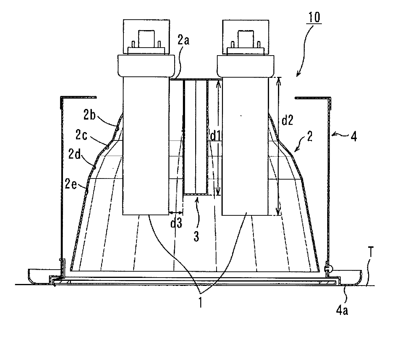
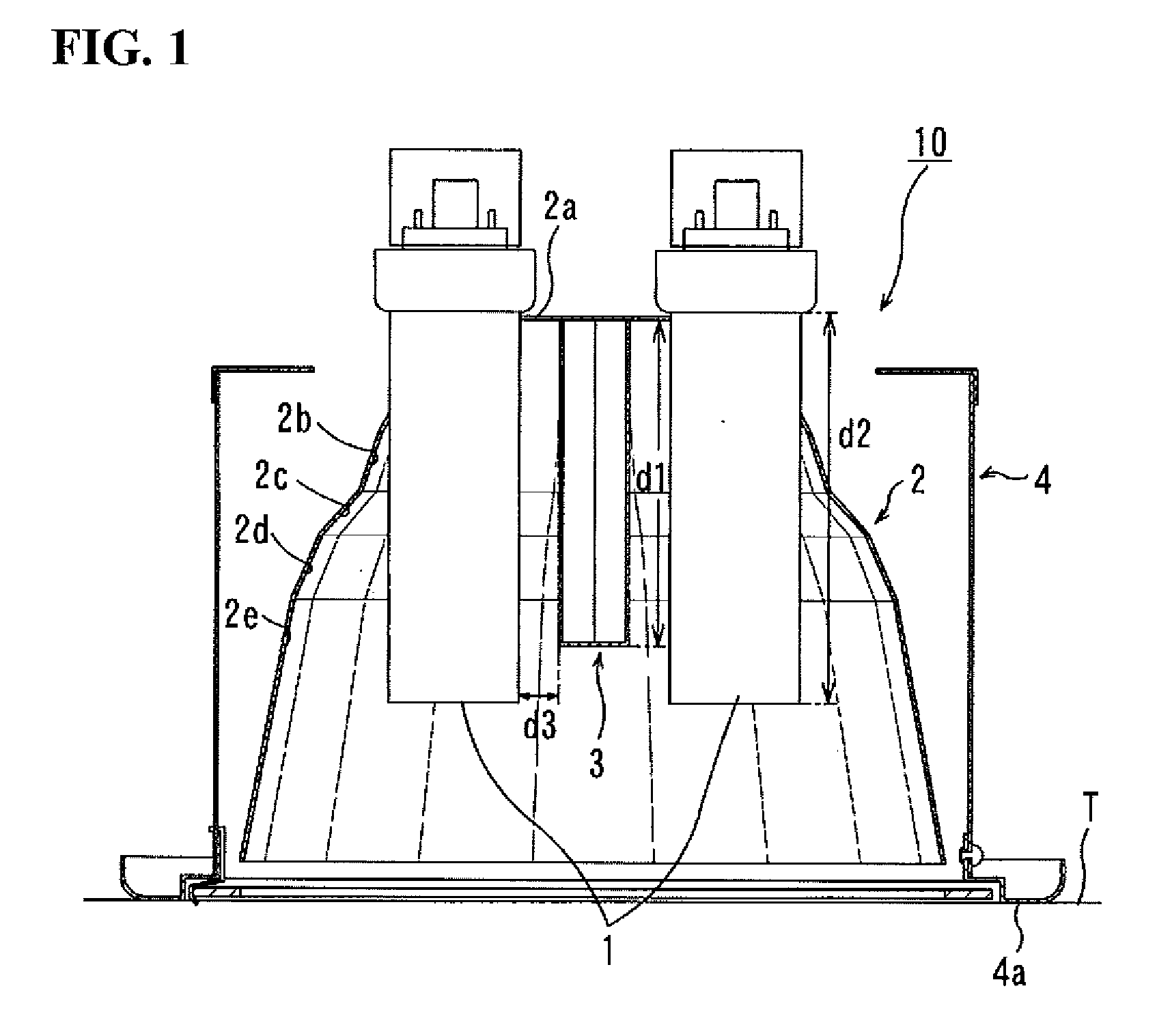
[0028]FIG. 1 is a sectional view showing a downlight fixture according to a first embodiment of the present invention, and FIG. 2 is a perspective view showing a reflector used in the downlight fixture in FIG. 1.
[0029]As shown in FIG. 1, the downlight fixture 10 comprises two bar-shaped light source lamps 1 each consisting of a fluorescent tube lamp, a reflector 2 for reflecting light from each of the bar-shaped light source lamps 1, a reflection member 3 for reflecting light from each of the bar-shaped light source lamps 1, and a lamp body 4 to which the reflector 2 is fixed.
[0030]Each of the two bar-shaped light source lamps 1 has an upper end portion (i.e., anchor portion) fixed to a vicinity of a top wall 2a (serving as an end wall) of the reflector 2, and a luminous portion (generally serving as an insertion portion) located inside the reflector 2 to protrude downwardly (i.e., toward an opening of the reflector 2). The two bar-shaped light source lamps 1 are d...
second embodiment
[Second Embodiment]
[0038]FIG. 4 is a sectional view showing a downlight fixture according to a second embodiment of the present invention, and FIG. 5 is a perspective view showing a reflector used in the downlight fixture in FIG. 4.
[0039]In the downlight fixture 10 illustrated in FIG. 4, three bar-shaped light source lamps 1 are inserted into the reflector 2 through respective ones of three cutouts 2f formed in the reflector 2.
[0040]Each of the three bar-shaped light source lamps 1 has an upper end portion (i.e., anchor portion) fixed to a vicinity of a top wall 2a (serving as an end wall) of the reflector 2, and a luminous portion (generally serving as an insertion portion) located inside the reflector 2 to protrude downwardly (i.e., toward an opening of the reflector 2). The three bar-shaped light source lamps 1 are disposed in such a manner that a distance between respective ones thereof gradually decreases in a downward direction, as shown in FIG. 4.
[0041]In the second embodimen...
third embodiment
[Third Embodiment]
[0047]FIG. 6 is a sectional view showing a downlight fixture according to a third embodiment of the present invention, and FIG. 7 is a perspective view showing a reflector used in the downlight fixture in FIG. 6.
[0048]In the downlight fixture 10 illustrated in FIG. 6, two bar-shaped light source lamps 1 are inserted into the reflector 2 through respective ones of two cutouts 2f formed in the reflector 2.
[0049]Each of the two bar-shaped light source lamps 1 has an upper end portion (i.e., anchor portion) fixed to a vicinity of a top wall 2a (serving as an end wall) of the reflector 2, and a luminous portion (generally serving as an insertion portion) located inside the reflector 2 to protrude downwardly (i.e., toward an opening of the reflector 2). The two bar-shaped light source lamps 1 are disposed to form a V shape, i.e., in such a manner that a distance between respective ones thereof gradually decreases in a downward direction, as shown in FIG. 6.
[0050]In the t...
PUM
Abstract
Disclosed is a lamp unit 10 which comprises a hat-shaped reflector 2 having an inner surface formed as a reflective surface for reflecting light, a plurality of bar-shaped light source lamps 1 each of which has an anchor end fixed to a vicinity of an end wall 2a of the reflector 2, and an insertion portion inserted inside the reflector 2 to protrude toward an opening of the reflector 2, and a reflection member 3 having an outer surface formed as a reflective surface. The reflection member 3 is disposed in a central region of the end wall 2a of the reflector 2 in such a manner to protrude toward the opening of the reflector 2. In the lamp unit, a protrusion length “d1” of the reflection member 3 is set in the range of one-third to three-fourths of a protrusion length “d2” of the insertion portion of each of the bar-shaped light source lamps 1. The present invention can optimize a positional relationship between the reflection member and each of the bar-shaped light source lamps so as to obtain enhanced illumination efficiency.
Description
BACKGROUND OF THE INVENTION[0001]1. Field of the Invention[0002]The present invention relates to a lamp unit suitable for a downlight fixture designed to be installed in a ceiling or the like of a building so as to illuminate a floor therebelow.[0003]2. Description of the Related Art[0004]In a lamp unit comprising a light source lamp and a reflector for reflecting light from the light source lamp, the reflector is a critical component having a great impact on illumination efficiency.[0005]The inventor of this application previously proposed a reflector generally configured as a hat-shaped polyhedron which has an inner reflective surface formed by two downwardly-stepped slant surfaces different in inclination angle, as disclosed in the following Patent Publication 1. The inventor also proposed to provide three or more downwardly-stepped slant surfaces, as disclosed in the following Patent Publication 2. In the reflector having the above multi-stepped structure, the respective inclina...
Claims
Application Information
Patent Timeline
Application Date:The date an application was filed.
Publication Date:The date a patent or application was officially published.
First Publication Date:The earliest publication date of a patent with the same application number.
Issue Date:Publication date of the patent grant document.
PCT Entry Date:The Entry date of PCT National Phase.
Estimated Expiry Date:The statutory expiry date of a patent right according to the Patent Law, and it is the longest term of protection that the patent right can achieve without the termination of the patent right due to other reasons(Term extension factor has been taken into account ).
Invalid Date:Actual expiry date is based on effective date or publication date of legal transaction data of invalid patent.

