
Isolated center tread rim idler

a center tread, idler technology, applied in the field of idlers, can solve the problems of generating noise and vibration that are detrimental to both the machine and its operator, affecting the operation of the machine, and the arrangement of the '211 patent may have limitations, and achieving the effect of less width

Active Publication Date: 2010-06-10
CATERPILLAR INC
View PDF25 Cites 20 Cited by
  • Summary
  • Abstract
  • Description
  • Claims
  • Application Information

AI Technical Summary

Benefits of technology

The present disclosure is about an isolated center tread rim idler and a method of assembling it. The idler includes an idler body and a circular rim with a narrow inner portion that fits around the idler body. The rim has a curved transition portion where a resilient ring engages. A side plate is attached to the idler body and includes a portion that engages the resilient ring. The method involves mounting a resilient ring on a side plate, positioning the idler body, and then positioning the circular rim with its transition portion in contact with the resilient ring. A second resilient ring is also positioned in contact with the circular rim and a side plate, and the side plates are fastened to the idler body. The technical effect of this invention is to provide an improved design for the isolated center tread rim idler that allows for better load distribution and reduced wear and tear.

Problems solved by technology

However, contact between the idler rim and the track bushings generate noise and vibrations that are detrimental to both the machine and its operator.
Although the rail vehicle wheel of the '211 patent may provide some damping of vibration and noise by employing elastic inserts, the arrangement in the '211 patent may have limitations.
This may lead to early failure of the elastic inserts.
Also, the arrangement of the rim relative to the elastic inserts and the wheel body may cause the elastic inserts of the '211 patent to potentially experience both tension and compression and incur destructive shear forces under side loading.
In addition, assembly of the wheel of the '211 patent may be problematic.
The shape and relationship of components in the '211 patent may render it difficult to property seat both annular elastic inserts during assembly.

Method used


Image

  • Isolated center tread rim idler
  • Isolated center tread rim idler
  • Isolated center tread rim idler

Examples


Embodiment Construction

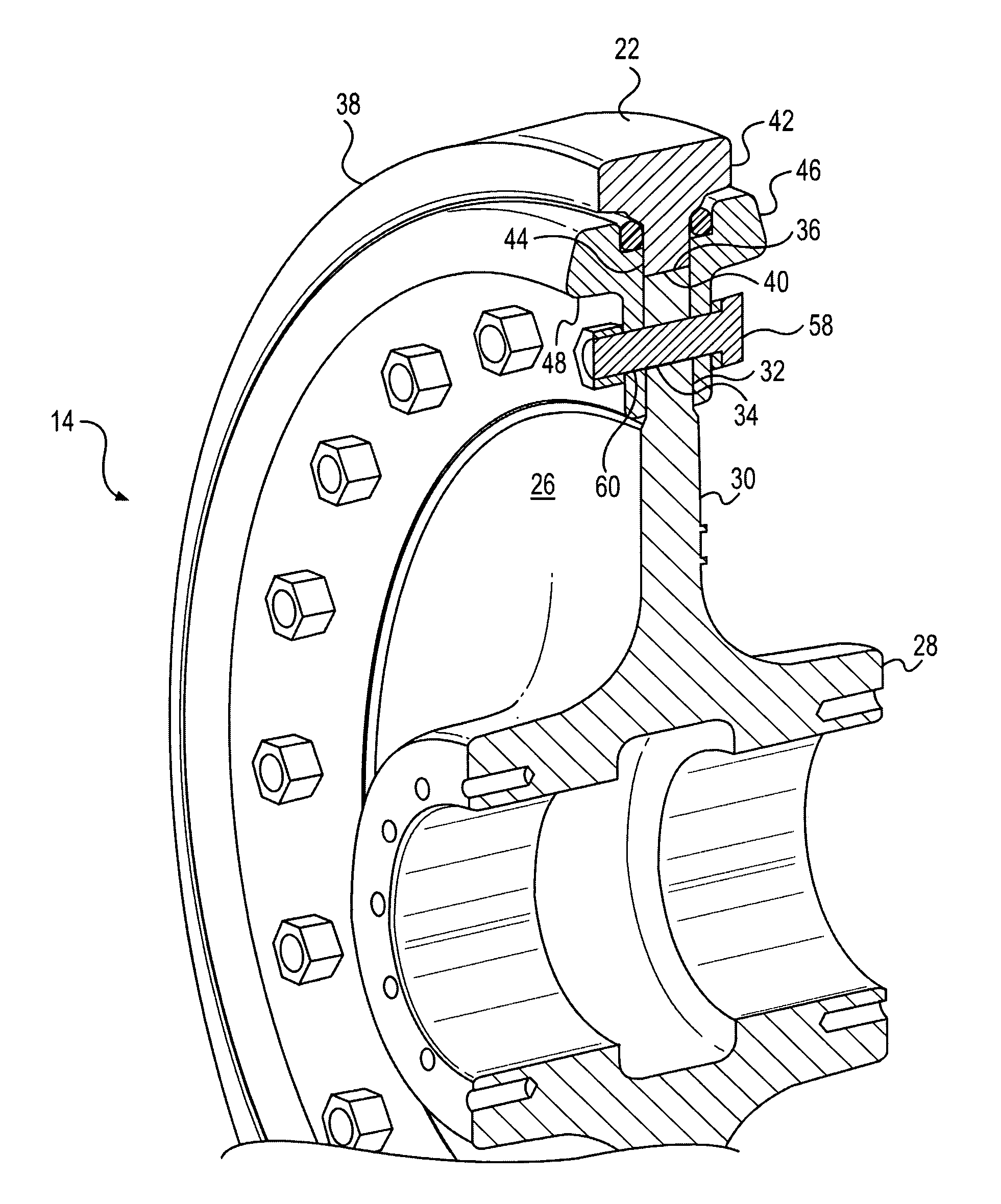
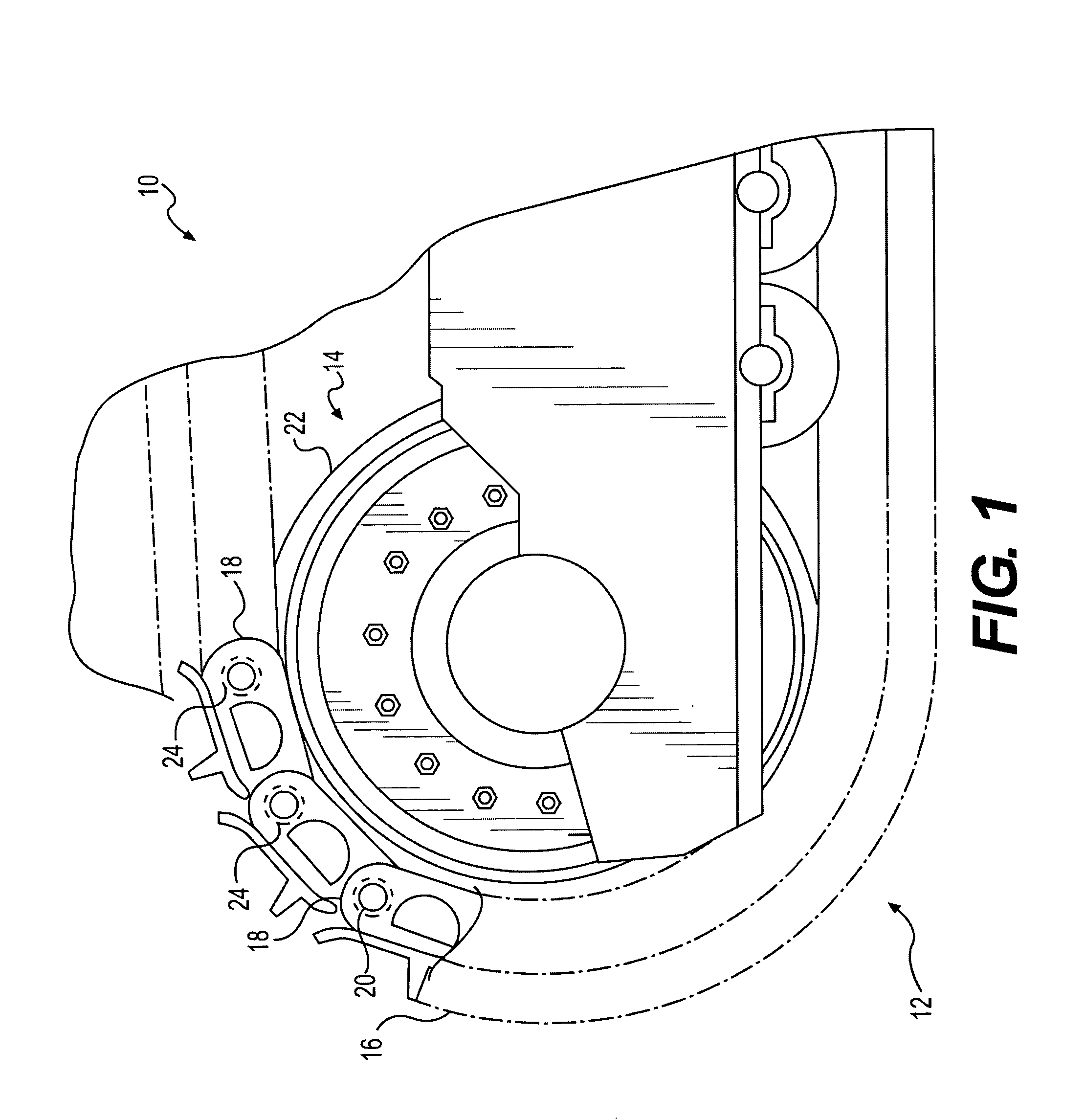
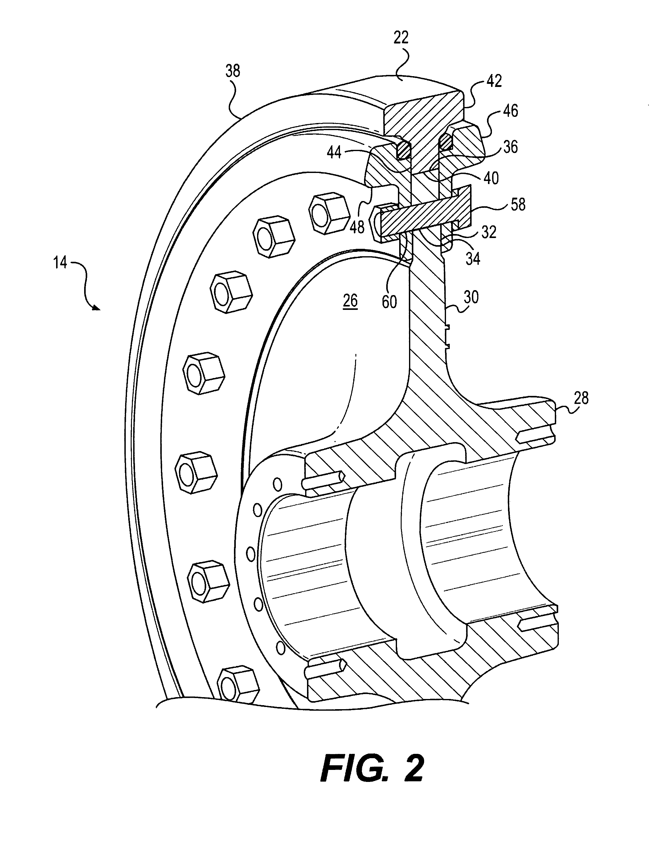
[0011]FIG. 1 is a partial view of a mobile machine 10, including a portion of a track assembly 12 associated with the mobile machine. Mobile machine 10 may be any of various mobile machines that employ track assemblies for ground transportation and / or for mobility during machine operation. For example, mobile machine 10 may be a track-type tractor, a tracked loader, a hydraulic excavator, or any other mobile machine. Track assembly 12 may include an idler assembly 14, cooperating with track 16 of track assembly 12. While only a portion of track assembly 12 is illustrated in FIG. 1, it will be understood that, in addition to idler assembly 14, a drive sprocket (not shown) and one or more other idler assemblies (also not shown), and other generally conventional track assembly components, may be associated with track assembly 12. Track 16 may include a plurality of links 18 connected by transverse track pins 20 and forming an endless loop about idler assembly 14, the drive sprocket (no...


PUM

PropertyMeasurementUnit
distanceaaaaaaaaaa
distanceaaaaaaaaaa
widthaaaaaaaaaa

Abstract

An isolated center tread rim idler is disclosed. The isolated center tread rim idler includes an idler body, and a circular rim including a radially outer portion configured to engage track bushings of a track assembly. The circular rim also includes a radially inner portion of less width than the radially outer portion. The radially inner portion is configured to cooperate with an outer circumferential surface of the idler body. The circular rim includes a curved transition portion between the radially outer portion and the radially inner portion. A resilient ring engages the curved transition portion. A side plate is fastened to a side of the idler body, and the side plate includes a portion engaging the resilient ring.

Description

TECHNICAL FIELD[0001]The present disclosure relates generally to an idler and, more particularly, to an isolated center tread rim idler.BACKGROUND[0002]Earthmoving equipment and construction machines such as, for example, hydraulic excavators and track-type tractors, are used to perform a variety of tasks, typically in rugged environments. In order to enable machine movement, one or more track mechanisms may be provided on such machines. Conventional track mechanisms may include a drive sprocket and one or more idlers to support and enable movement of a ground engaging track about the drive sprocket and idler(s). A track idler may rotate about an axis, and may include a rim portion that engages a plurality of track link members that are interconnected by spaced track pins. Some idlers, for example center tread idlers, engage bushings extending between the laterally spaced links of a track mechanism. The drive sprocket, in combination with the engagement between the idler rim and the...

Claims


Application Information

Patent Timeline
Patent Type & Authority Applications(United States)
IPC IPC(8): B62D55/08B23P11/00
CPCB62D55/0966
Inventor ANGOT, DANIELJIANG, XIANGYANG
Owner CATERPILLAR INC
Learn More