
Precise location and orientation of a concealed dipole transmitter

a dipole transmitter and precise technology, applied in the direction of reradiation, instrumentation, electromagnetic wave detection, etc., can solve the problems of substantial damage to property, death, and hidden dangers of people, and achieve the effect of reducing the risk of accidental death, and reducing the detection efficiency of the effect of detecting the location of the concealed dipole transmitter

Active Publication Date: 2010-06-10
BUSAN TRANSPORTATION CORPORATION
View PDF19 Cites 77 Cited by
  • Summary
  • Abstract
  • Description
  • Claims
  • Application Information

AI Technical Summary

Benefits of technology

[0007]Consistent with some embodiments of the present invention, a method for determining the location and orientation of a sonde includes measuring a set of complex electromagnetic field magnitude and phase strengths at one or more positions while traversing a target sonde path at any angle using one or more electromagnetic coil sensors, modeling a set of expected complex electromagnetic strengths of a hypothetical sonde at each of the one or more positions for one or

Problems solved by technology

Underground pipes and conduits are often buried and not readily accessible.
If the location of buried utilities and / or underground drill heads are not accurately known during excavation and / or boring, substantial destruction to property, serious physical harm to a person, or even death may occur.
Conventional EM locators, however, do not provide for precise determination of the location and orientation of sondes and exhibit some practical use limitations relating to the geometric relationship between the EM locator receiver and the sonde transmitter.

Method used


Image

  • Precise location and orientation of a concealed dipole transmitter
  • Precise location and orientation of a concealed dipole transmitter
  • Precise location and orientation of a concealed dipole transmitter

Examples


Embodiment Construction

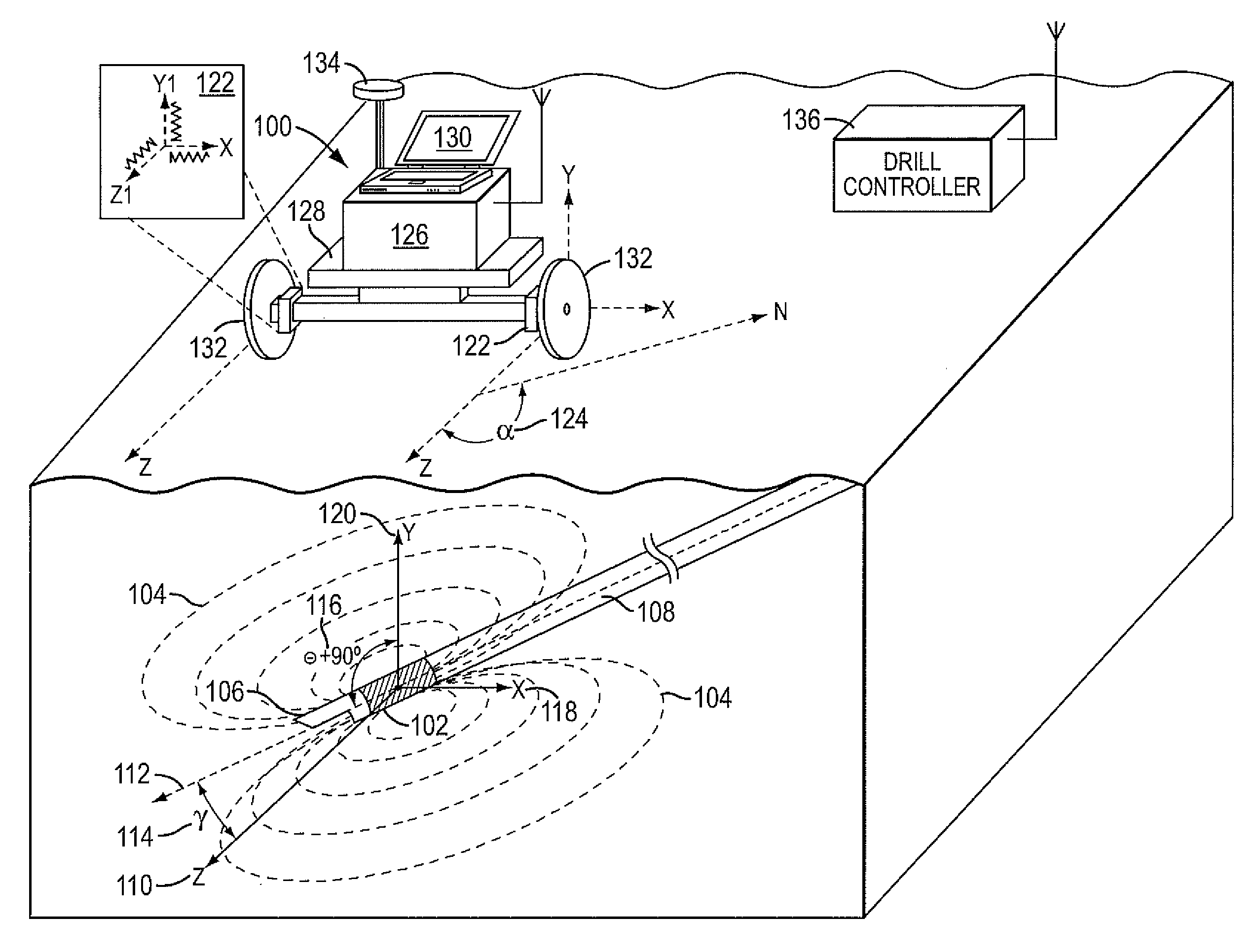
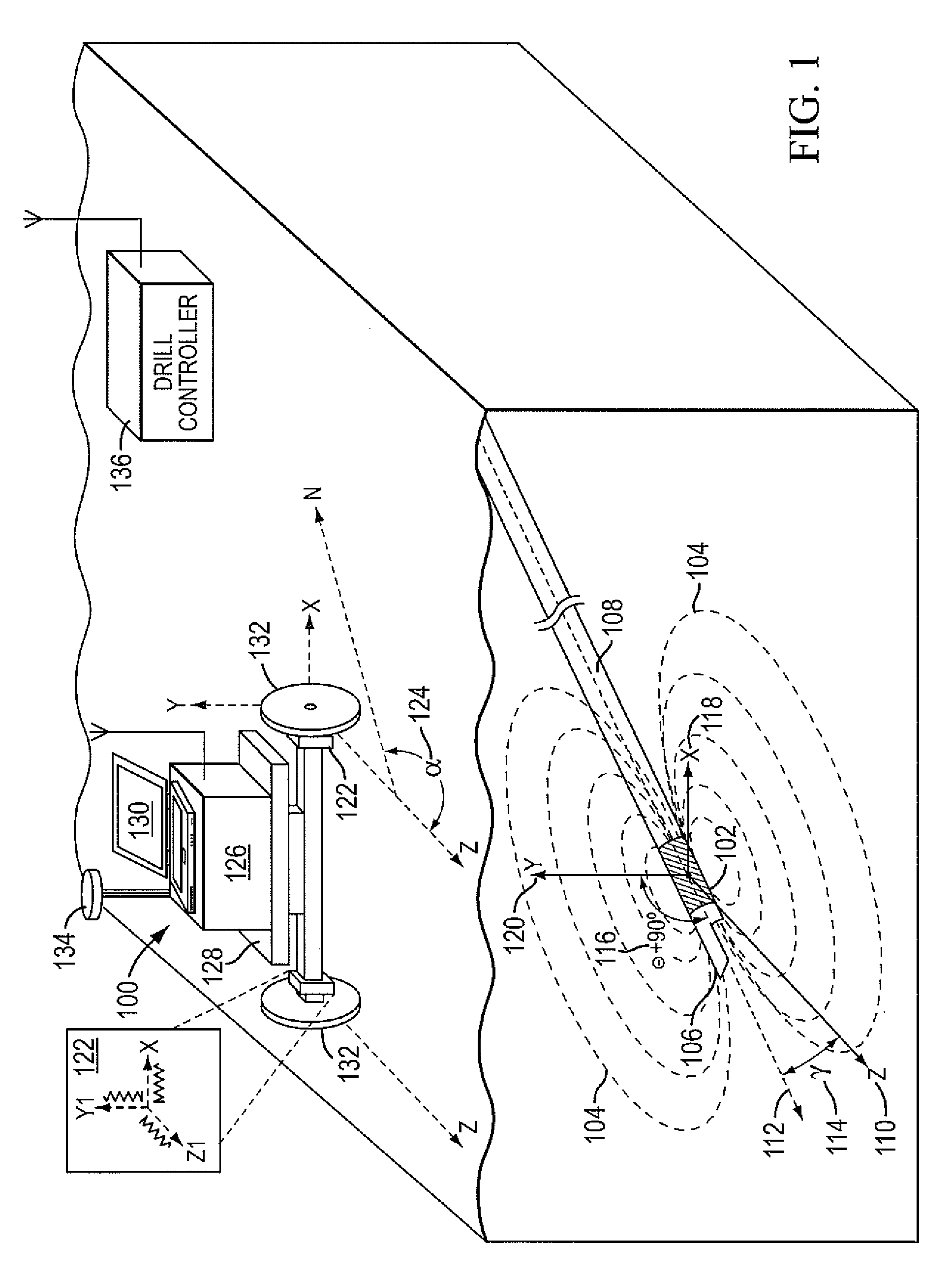
[0035]As discussed above, EM locators typically include a receiver and a transmitter, which may be a radiating underground conductor. In some applications, a radiating underground conductor is a linear pipe or cable and the EM locator is configured to estimate the position of the underground pipe or cable. Sonde position estimation differs from the methods used for linear pipe or cable location, however, because the EM field emitted by the sonde is three dimensional and, accordingly, represented by magnetic dipole equations, which describe the decaying field strength of the EM field as the cube of the distance from the sonde. See e.g., Gard, “Magnetic Field Sensing in the Underground Construction Environment”, Sensors for Industry Conference, Houston, Tex., November 2002 (“Gard”). Traditional EM locators designed for locating a continuous conducting pipe or cable designed to function as a transmitter have a single measurement axis and thus suffer from the “ghost” problem. See. e.g.,...


PUM


Abstract

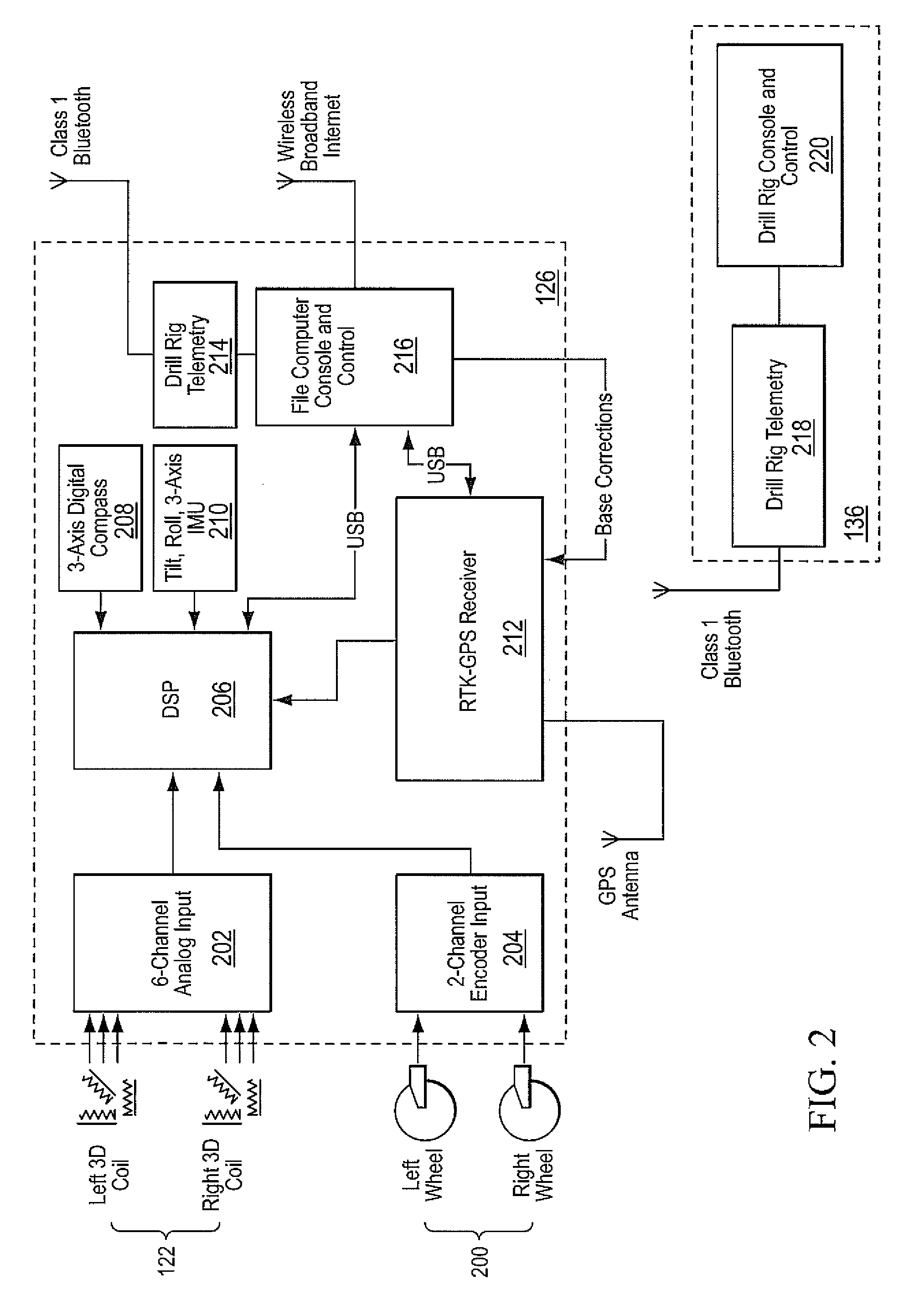
A method for determining the location of an underground sonde transmitter is disclosed. In some embodiments, the method includes measuring a set of complex electromagnetic field magnitude and phase strengths at one or more of positions while traversing a target sonde path at any angle using one or more electromagnetic coil sensors, modeling a set of expected complex electromagnetic strengths of a hypothetical sonde at the one or more of positions for one or more of the electromagnetic coil sensors, the set of expected electromagnetic field values corresponding to a model for the target sonde, and estimating parameters related to the target sonde based on the residual error between the measured set of complex electromagnetic field values and the modeled set of expected complex electromagnetic field strengths, wherein a final estimated parameter set is determined after the residual error has converged to a minimum tolerance.

Description

BACKGROUND[0001]1. Field of the Invention[0002]The present invention relates to a method and apparatus for detecting a location of concealed dipole transmitters and, in particular, to the precise determination of the location and orientation of such transmitters without restriction on the geometrical relationship between a receiver and the transmitter.[0003]2. Discussion of Related Art[0004]Underground pipes and conduits are often buried and not readily accessible. It is often necessary to locate these concealed utility conduits in order to repair and replace them. It is also important to know the location of underground utilities so that excavators can avoid them while excavating an area. Further, it is often necessary to locate the position of a drill head of a directional boring machine capable of trenchless underground drilling during a boring operation. If the location of buried utilities and / or underground drill heads are not accurately known during excavation and / or boring, s...

Claims


Application Information

Patent Timeline
IPC IPC(8): G01V3/12G06F19/00
CPCG01V3/12
Inventor OVERBY, JOHANWAITE, JAMES W.GARGOV, DIMITARLI, KUN
Owner BUSAN TRANSPORTATION CORPORATION
Learn More