
RF magnetic field homogeneity and magnetic resonance image uniformity using inductive coupling

a magnetic field and inductive coupling technology, applied in the field of improving magnetic resonance imaging quality, can solve the problems of poor coupling between primary transmit antenna and secondary resonator, affecting the resonant frequency of secondary resonators, and interference can be subject to spatial effects, so as to improve image quality and improve field uniformity

Active Publication Date: 2020-12-31
UNITED STATES OF AMERICA
View PDF0 Cites 4 Cited by
  • Summary
  • Abstract
  • Description
  • Claims
  • Application Information

AI Technical Summary

Benefits of technology

The patent text describes a method of improving magnetic resonance imaging (MRI) by using two resonance frequencies: a first frequency for a passive circuit and a second frequency for a second antenna. The passive circuit is adjusted to have its resonance frequency when the MRI system is in its first operating environment, which is proximate to the sample. The first frequency is above the MRI system's operating frequency but below its second operating frequency. The method allows for improved field uniformity and image quality when acquiring MRI signals at the first frequency. Additionally, the second antenna is adjusted to have a resonance frequency above the MRI system's second operating frequency to improve RF magnetic field uniformity at the second operating frequency. The first or second antenna can be adjustable and incorporate adjustable components. Overall, the method improves MRI image quality and provides better information on the sample being imaged.

Problems solved by technology

However, the physical embodiment can be subject to spatial effects and parasitic effects whereby the ordering of components can make a practical difference.
Exchanging secondary resonators between FIGS. 6A-6B would lead to poor coupling between primary transmit antenna and secondary resonator.
The presence of water or other materials in a sample placed in the MRI sample volume, and subject to both primary and secondary RF magnetic fields, can cause loading of a secondary resonator which can affect its resonant frequency.
As discussed herein, having B1L out of phase with B1T causes the gradients of these two fields to reinforce each other, leading to increased field variations and worsened field uniformity in the sample volume between LT and LL.
This limited RF magnetic field (B1) uniformity can be problematic when attempting to image even relatively small volumes of an animal.
That is, the large regions of pale pink shading are an artifact of the clipped color temperature scale, and are not at all indicative of field uniformity.
That is, high standard deviation detracts from image quality even if SNR is high: the “Without” configuration suffers from precisely this problem.
Also, having low standard deviation is not advantageous if SNR is also low, as shown in the “Opposing” configuration, where the phantom image is barely discernible over the noise.
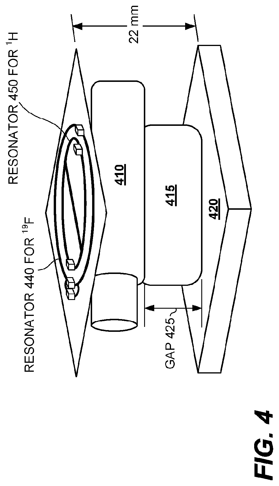
However, secondary resonator 3040, having a resonant frequency close to a frequency of operation, can adversely affect field uniformity of the transmit B1+ magnetic field, as shown in FIGS. 34-35. FIG. 34 shows simulation results for B1+ amplitude (|B1+|) for various cross-sections of the phantom and various configurations of the disclosed technology.
It can be observed that the secondary resonator 3040 adversely impacts the |B1+| uniformity in this configuration.
This image has marked non-uniformity and very low sensitivity in the top half of the image.
However due to component variations, a perfect match may not be achieved.

Method used


Image

  • RF magnetic field homogeneity and magnetic resonance image uniformity using inductive coupling
  • RF magnetic field homogeneity and magnetic resonance image uniformity using inductive coupling
  • RF magnetic field homogeneity and magnetic resonance image uniformity using inductive coupling

Examples


example symmetry

Considerations

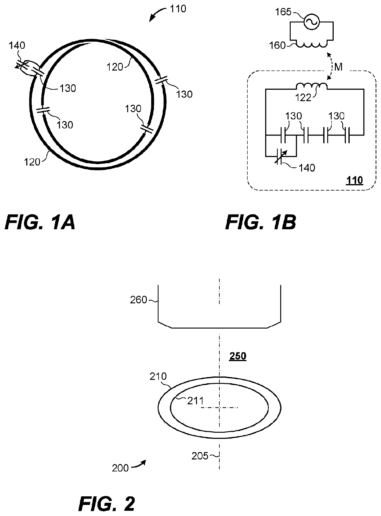
[0114]FIGS. 6A-6B show different symmetry relationships between primary and secondary magnetic fields. For clarity of illustration, FIGS. 6-7 show the shapes of transmit antennas and secondary resonators in oblique view; details such as discrete components, adjustable components, or numbers of loops have been omitted.

[0115]FIG. 6A shows an MRI configuration in which primary transmit antenna 660 and secondary resonator 610 are both nominally circular, with a common axis of symmetry 605, and are situated on opposite sides of a sample volume 650. In such a configuration, antenna 660 generates a primary magnetic field 662 shown by solid lines. The changing magnetic flux through the secondary resonator 610 generates a secondary magnetic field 612 as shown by dashed lines, when the secondary resonator 610 is tuned as disclosed herein. In this configuration, the primary component of the RF magnetic field in the sample volume is parallel to the axis 605.

[0116]FIG. 6B shows an ...

example method

[0137]Because of loading, it can be desirable to tune the resonant frequency of a secondary resonator prior to imaging, to provide a substantially optimized shimming of the RF magnetic field, to increase signal to noise ratio and reduce standard deviation of imaging sensitivity across a region of interest of a sample within the MRI system's sample volume.

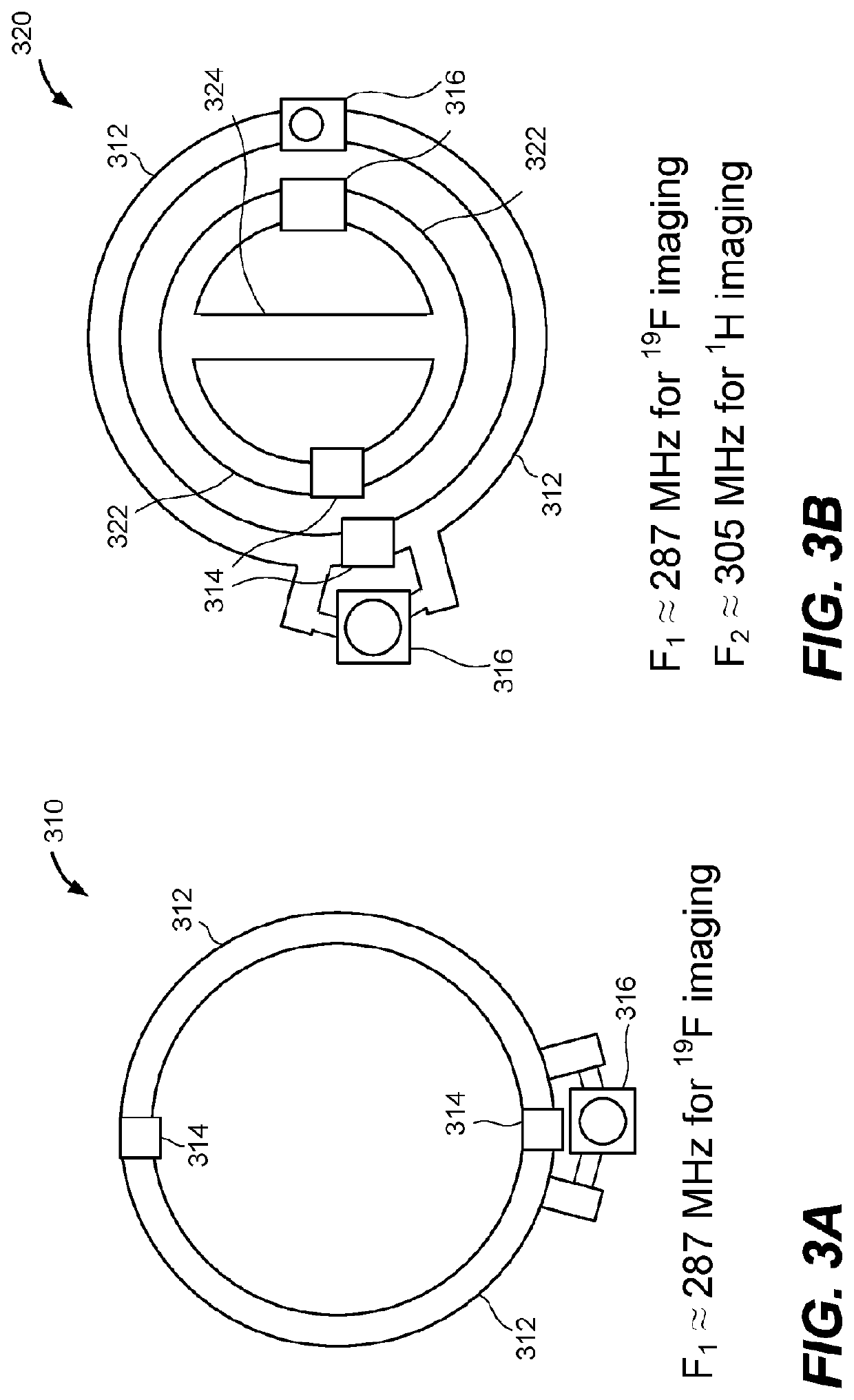
[0138]FIG. 10 describes an example method. At process block 1010, a secondary resonator, which can be similar to one of the passive circuits described herein, is tuned to a first resonant frequency while situated in an operating environment, near to a sample in the sample volume of an MRI system. For imaging a first nuclide (e.g. 19F) at a first operating frequency of the MRI system, the first resonant frequency is above the first operating frequency, and below a second operating frequency of the MRI system. At process block 1020, MRI signals are acquired at the first operating frequency.

[0139]In some embodiments, the method can be ...

example mri

Machine

[0146]FIG. 13 shows an example MRI machine 1300 incorporating the disclosed technology. The MRI machine 1300 incorporates a system 1200 as described above, incorporating two transmit antennas and at least one secondary resonator about a sample volume 1250 of the MRI machine 1300. MRI machine 1300 can additionally incorporate other components and subsystems, including one or more of: main field magnet 1314 and power supply 1316; gradient field magnets 1324 and power supply 1326; RF magnet power supply 1336; controller 1370; power subsystem 1381; or mechanical subsystem 1383. The mechanical subsystem can include one or more of: a translation stage, a sample container, or a belt or clamp to fasten a sample within sample volume 1250. The MRI machine 1300 can further include a computing node 1375, incorporating one or more processors with memory coupled thereto, and operable to acquire first MRI signals of a first nuclide at a first operating frequency and to acquire second MRI si...


PUM


Abstract

An apparatus, method, and system are disclosed for improving uniformity of RF magnetic field in an MRI system, and thereby improving both signal-to-noise ratio and uniformity of imaging sensitivity across a sampling volume, to provide more uniform MRI images. A passive LC resonator develops induced EMF and induced currents in a primary RF magnetic field; the secondary magnetic field produced thereby can counteract magnetic field amplitude gradients to produce a more homogeneous RF magnetic field. In systems with separate transmit and receive coils, a shunt detuning circuit is pulsed ON to prevent interference during the transmit period. In a dual-frequency MRI machine (e.g. 19F and 1H), the RF magnetic field at the lower operating frequency can be homogenized by tuning the resonance of the passive resonator between the two operating frequencies. Another resonator can improve RF field uniformity at the higher operating frequency. Variants and experimental results are disclosed.

Description

CROSS REFERENCE TO RELATED APPLICATIONS[0001]This application claims priority to U.S. Provisional Application No. 62 / 579,014, filed Oct. 30, 2017, which is incorporated by reference in its entirety.FIELD[0002]The disclosure pertains to improvement of magnetic resonance imaging (MRI) quality in an MRI system using inductive coupling.BACKGROUND[0003]MRI technology continues to advance through the development of new magnets, new pulse sequences, new analytic and image processing techniques, and joint imaging modalities. Different classes of MRI systems are available for whole body applications, brain studies, animal studies, and magnetic resonance microscopy. MRI is used to acquire cross-sectional images, study functional activity, diagnose disease, and measure tissue perfusion within human bodies and other organisms. In addition to medical applications, MRI has also been applied to diverse fields including oil exploration and is gradually finding use for imaging non-living solid objec...

Claims


Application Information

Patent Timeline
Patent Type & Authority Applications(United States)
IPC IPC(8): G01R33/36G01R33/565
CPCG01R33/5659G01R33/3642G01R33/3635
Inventor PARK, BU S.MCCRIGHT, BRENTONRAJAN, SUNDER S.
Owner UNITED STATES OF AMERICA
Learn More