
Shimming coil optimization design and manufacturing method and structure thereof

A shimming coil and optimized design technology, which is applied in coil manufacturing, coils, steering induction equipment, etc., can solve the problems of coil magnetic field uniformity requirements and coil volume constraints that are difficult to meet at the same time, and the volume of shimming coils is large, so as to reduce the Effect of stray magnetic field and guarantee of magnetic field accuracy

Pending Publication Date: 2019-07-30
GENERAL ENG RES INST CHINA ACAD OF ENG PHYSICS
View PDF0 Cites 4 Cited by
  • Summary
  • Abstract
  • Description
  • Claims
  • Application Information

AI Technical Summary

Problems solved by technology

Its core sensitive element is the atomic gas chamber, which is filled with alkali metal atoms, inert gas atoms and buffer gas. The shim coil is an important component of the nuclear magnetic resonance gyroscope (Nuclear Magnetic Resonance Gyroscope, NMRG), which is the atomic gas chamber in the NMRG. Provide a high uniform working magnetic field. With the development of NMRG towards miniaturization, the volume of existing shim coils is relatively large, and there is a problem that it is difficult to meet the requirements of coil magnetic field uniformity and coil volume constraints at the same time.

Method used


Image

  • Shimming coil optimization design and manufacturing method and structure thereof
  • Shimming coil optimization design and manufacturing method and structure thereof
  • Shimming coil optimization design and manufacturing method and structure thereof

Examples


Embodiment 1

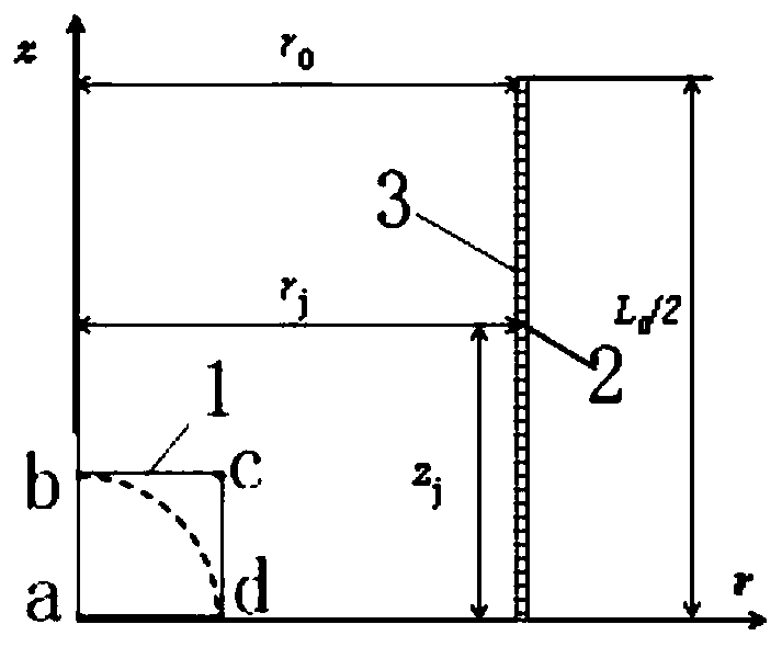
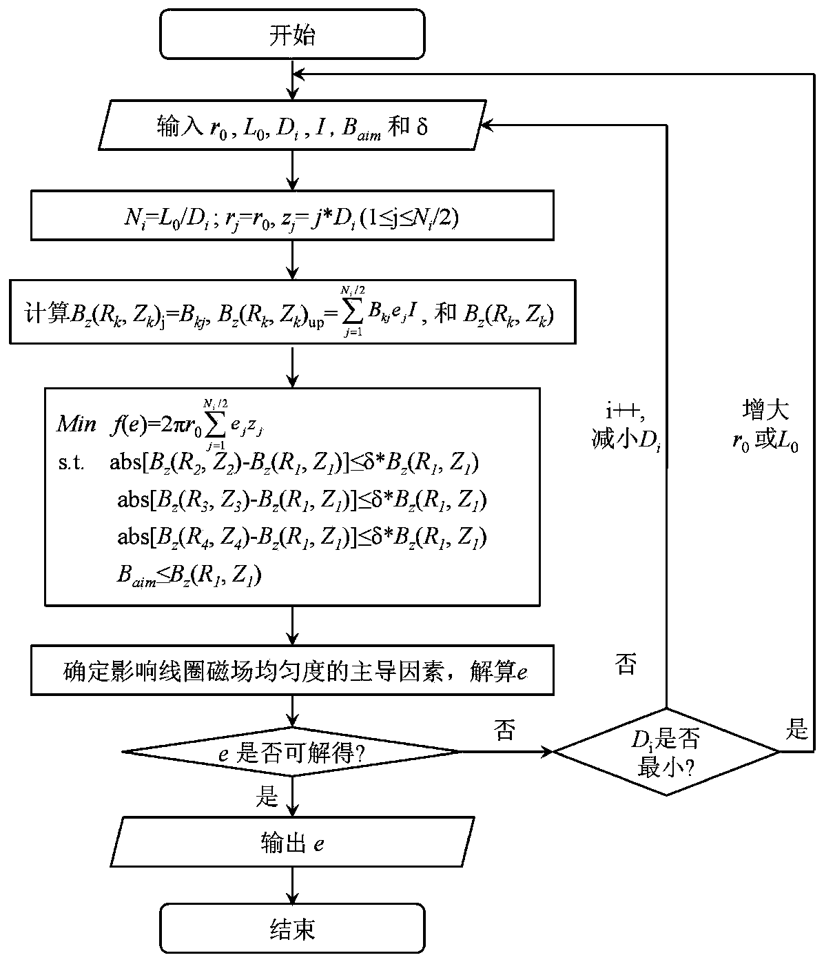
[0050] Example 1, as figure 1 , figure 2 shown;

[0051] The optimal design of the shim coil includes the following steps:

[0052] S1. Determine the parameters to be optimized related to the uniformity δ of the magnetic field of the coil and the size of the volume. The parameter to be optimized is the radial size r of the coil 0 , Axial dimension L 0 , the wire diameter D, the number of coil turns m, and the state variable e that characterizes the existence of the energized winding j;

[0053] S2. Determine the optimization process, establish an optimization model, use the optimization model to obtain the optimal solution that satisfies the constraints, and determine r 0 , L 0 , D, m and e values;

[0054] S3. According to r in the optimal solution 0 , L 0 , D, m and e, design and manufacture the shim coil with the smallest volume that satisfies the constraints of magnetic field amplitude and uniformity δ.

[0055] The following steps are included in S2:

[0056] S...

Embodiment 2

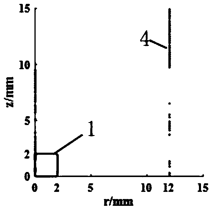
[0064] Example 2, figure 1 , figure 2 , image 3 , Figure 4 shown,

[0065] According to the overall design layout of the NMRG, the radial and axial dimensions r of the initial feasible current-carrying domain 3 are preliminarily determined 0 and L 0 They are 12mm and 30mm respectively, and the target shimming area 1 is a cylindrical area with a diameter of 4mm in the center of the coil and a length of 4mm. Determine the target shimming area 1 magnetic field B z The minimum amplitude B required to be reached aim is 50 amplitude, the coil current I is 100mA, and the magnetic field uniformity δ of the target shimming area 1 is 1 / 10 5 , the initial wire diameter D of the coil i is 1mm, the number of turns and wire diameter of the optimized coil are 82 turns and 0.2mm, respectively. The number of turns distribution of the optimized cylindrical coil (1 / 4 axisymmetric area) is as follows image 3 shown. The axial magnetic field uniformity δ of the optimized cylindrical c...

Embodiment 3

[0066] Example 3, as Figure 5 , Image 6 , Figure 7 shown,

[0067] A method for making a shim coil, comprising the following steps;

[0068] S1, according to r in the optimal solution 0 and L 0 The value of , determines the length and width of the flexible substrate 7;

[0069] S2. According to the value of D in the optimal solution, select the energized wire 9 of the corresponding diameter;

[0070] S3, install the energized wire 9 on the flexible substrate 7, and determine the number of turns and the installation position of the energized wire 9 on the substrate 7 according to the values ​​of m and e in the optimal solution;

[0071] S4. The input wire 11 is communicated with the input end of the first row of energized wires 9, a plurality of connection wires are arranged in the middle of the substrate 7, and the plurality of connection wires are arranged in a row, and the output end of the nth row of energized wires 9 is connected to the The input end of the energ...


PUM


Abstract

The invention discloses a shimming coil optimization design and manufacturing method and a structure thereof, and relates to the technical field of the nuclear magnetic resonance gyroscope. The designflow is as follows: S1, determining to-be-optimized parameters r0, L0, D, m and e; S2, establishing an optimization model, and determining r0, L0, D, m and e; S3, designing a shimming coil satisfyingthe minimum constraint condition volume; the manufacturing method comprises the following steps: S1, determining a substrate; S2, selecting electrifying conductors; S3, mounting the electrifying conductors on the substrate; S4, communicating each line of electrifying conductor; and S5, plugging a male connector and in a female connector. The shimming coil manufactured through the method can control the coil volume when the coil magnetic field amplitude and the uniformity constraint are satisfied; the current direction of the electrifying conductor is vertical to a central axis of the substrate, and the stray magnetic field is reduced; the output conductor and the connecting line are arranged with the same current size and opposite directions, the stray magnetic field produced by the connecting line can be counteracted, and the coil magnetic field precision is guaranteed.

Description

technical field [0001] The invention relates to the technical field of nuclear magnetic resonance gyroscopes, in particular to an optimal design, a manufacturing method and a structure of a shim coil. Background technique [0002] The Nuclear Magnetic Resonance Gyroscope (NMRG) has the advantages of high precision, small size, and high environmental adaptability, and has become the first generation of inertial navigation gyroscopes developed by countries. NMRG measures the angular velocity of a moving carrier based on the principle of nuclear magnetic resonance. The core sensitive element is the atomic gas chamber, which is filled with alkali metal atoms, inert gas atoms and buffer gas. The shim coil is an important component of the Nuclear Magnetic Resonance Gyroscope (NMRG), which is the atomic gas chamber in the NMRG. Provide a highly uniform working magnetic field. With the development of NMRG towards miniaturization, the existing shim coils are too large, and there are...

Claims


Application Information

Patent Timeline
IPC IPC(8): G01C19/60H01F41/04H01F5/04H01F5/00
CPCG01C19/60H01F41/04H01F5/00H01F5/04
Inventor 邓东阁朱明智舒强汪宝旭杨飞吴文凯邱勇
Owner GENERAL ENG RES INST CHINA ACAD OF ENG PHYSICS
Learn More