
Mine roof monitoring apparatus

Inactive Publication Date: 2010-06-10
ROBERTSON JR ROY LEE
View PDF15 Cites 11 Cited by
  • Summary
  • Abstract
  • Description
  • Claims
  • Application Information

AI Technical Summary

Benefits of technology

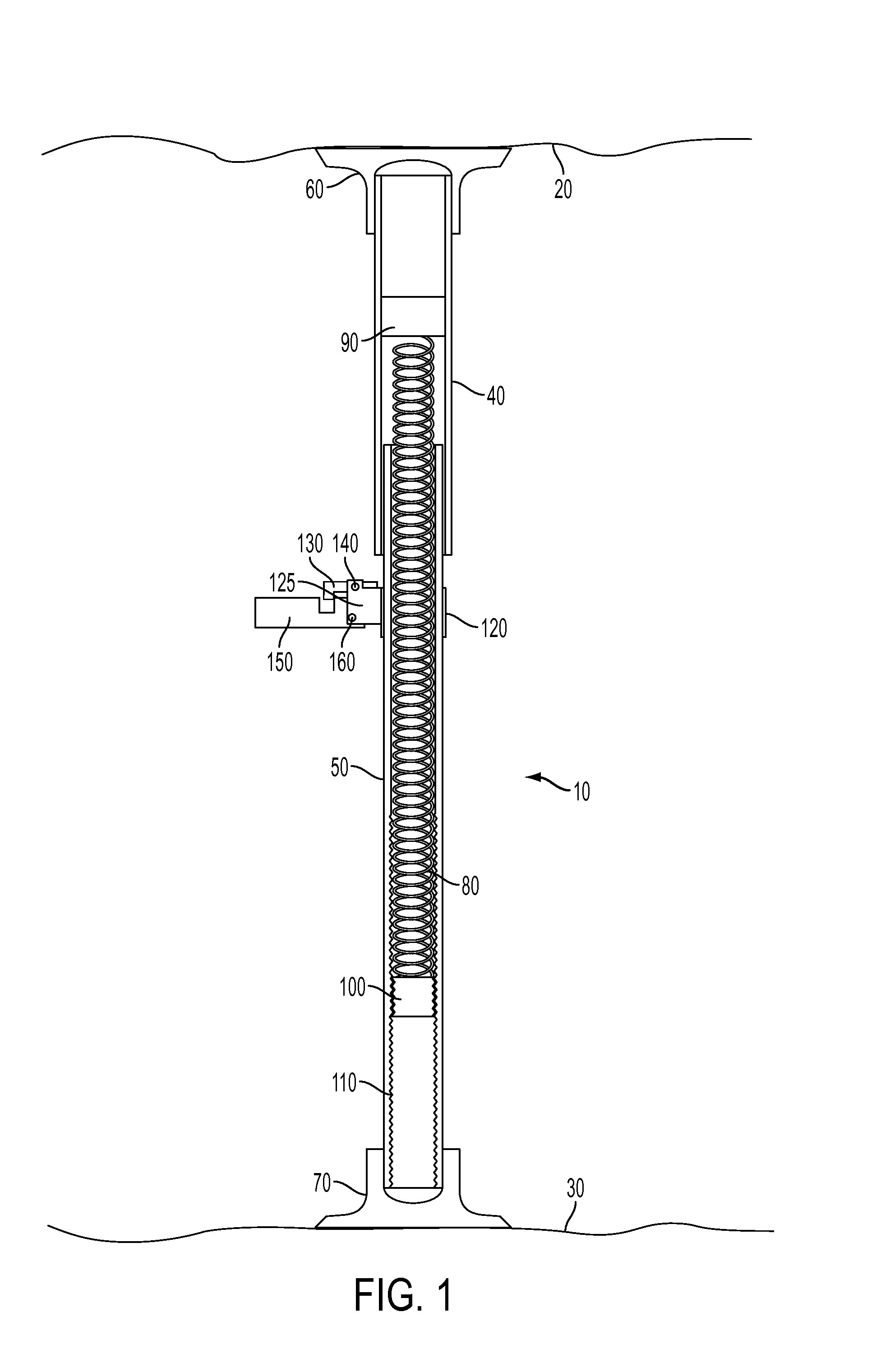
[0011]In one embodiment, the apparatus comprises a spring loaded rod or post having at least two slidably interconnected tubes. The embodiment has an out tube and an inner tub that slidably fits into the outer tube. A spring having an end anchored in each tube allows the tubes to be compressed with respect to each other and the allowed to expand again. In use, the post is compressed to position it in between the roof and floor of a mine shaft and the spring keeps the rod in place. A flag mechanism is mounted on one of the slidably interconnected tubes. When a mine roof subsides and causes the interconnected tubes to move a predetermined distance with respect to each other, the flag mechanism is tripped. This indicates that the mine roof has subsided at least the distance required to trip the flag, warning anyone observing the monitor that there has been a shift in the roof. By effectively monitoring the distance between the floor and roof of the mine shaft, the present invention in its various embodiments can detect movements of the roof, including in cases that might be missed by a monitor that is mounted in the roof.

Problems solved by technology

When the mine roof subsides a sufficient amount, the latch is tripped and the flag falls from its initial position.
When a mine roof subsides and causes the interconnected tubes to move a predetermined distance with respect to each other, the flag mechanism is tripped.

Method used


Image

  • Mine roof monitoring apparatus
  • Mine roof monitoring apparatus
  • Mine roof monitoring apparatus

Examples


Embodiment Construction

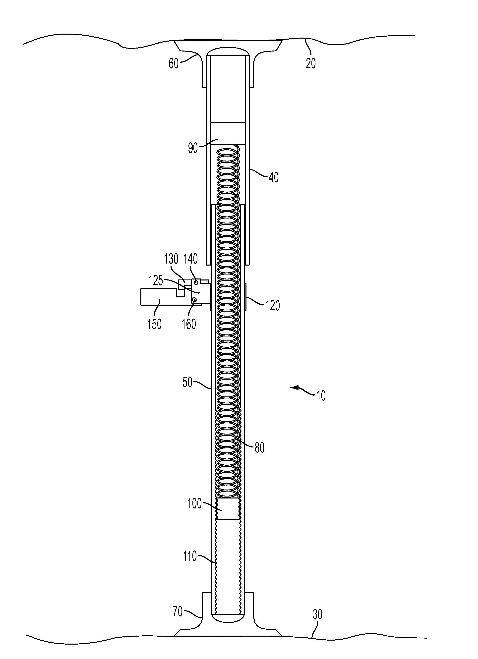
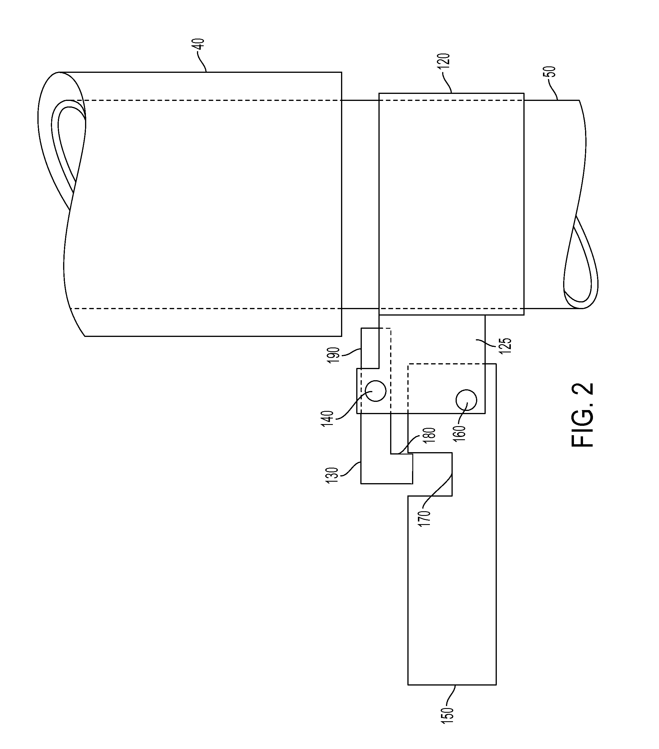
[0021]FIG. 1 shows an embodiment of the mine roof monitoring apparatus 10 installed between a mine roof 20 and mine floor 30 of an underground mine. The mine roof monitoring apparatus 10 has a first contact member comprised of an outer tube 40 and a second contact member comprised of an inner tube 50. Inner tube 50 slidably fits within outer tube 40. On the distal end of outer tube 40 is a head plate 60 which contacts the roof 20 of the mine. On the distal end of inner tube 50 a foot plate 70 is attached which contacts the floor 30 of the mine. A compression spring 80 within the body of the mine roof monitoring apparatus 10 allows outer tube 40 and inner tube 50 to be compressed toward each other for installation and allowed to expand to maintain contact between the mine roof 20 and floor 30. Head plate 60 and foot plate 70 can compensate for uneven surfaces and, in some case, allow an embodiment of the mine roof monitoring apparatus to be installed at an angle from vertical. Altern...


PUM


Abstract

A mine roof monitoring apparatus has at least two contact members. At least one contact member maintains contact with the roof of a mine shaft. At least one contact member maintains contact with a floor of the same mine shaft. A motion monitoring apparatus monitors the relative motion between the two contact members, and a flag on the motion monitoring apparatus changes position, when a predetermined amount of motion occurs between the two contact members. This indicates that the roof of the mine shaft has subsided enough to move the respective contact member.

Description

[0001]This application claims priority from U.S. Provisional Application 61 / 120,008, filed on Dec. 4, 2008. The entire disclosure contained in U.S. Provisional Application 61 / 120,008, including the attachments thereto, are incorporated herein by reference.BACKGROUND OF THE INVENTION[0002]Cave-ins are a very significant safety hazard in mines. Mine shafts sometimes experience cave-ins, collapses, or falling rock due to the layered and stratified makeup of the earth. Frequently, a cave-in is presaged by a measurable sag or subsidence of the roof of the mine shaft. This subsidence may result from the separation of rock layers or other geologic mechanisms and the subsidence of the roof may occur at various depths up into the roof of the mine.[0003]Many prior art devices for monitoring mine roofs are mounted in holes bored into the roof of the mine. These are only capable of monitoring the roof rock up to the depth of the hole, because the measurement being monitored is from the surface ...

Claims


Application Information

Patent Timeline
IPC IPC(8): G08B21/00
CPCG08B13/1436G08B13/08
Inventor ROBERTSON, JR., ROY LEE
Owner ROBERTSON JR ROY LEE
Learn More