Luminaire

Inactive Publication Date: 2010-06-10
TOSHIBA LIGHTING & TECH CORP +1
View PDF4 Cites 68 Cited by
  • Summary
  • Abstract
  • Description
  • Claims
  • Application Information

AI Technical Summary

Benefits of technology

[0010]A luminaire according to an embodiment of the invention is securely installed in a part, such as a ceiling, and is simplify the installation operations. The luminaire comprises a light-emitting unit, a main body frame, a support frame, and a lighting unit, for example. The light-emitting unit comprises light-emitting elements. The main body frame supports t

Problems solved by technology

Since the installation operation of the lighting apparatus on a′ ceiling is required to perform in high places, the operation is difficult.
Thus, the installation operation includes troublesome steps, and the lighting apparatus may not be securely installed.
Thus, if the main unit assembled with a lighting unit is very heavy, the lighting apparatus may not be securely installed.
Particularly, if the lighting apparatus is very large, the equipment may not be supported by sufficient strength.
The installation operation is difficult, because the operation must be performed while supporting a relatively heavy part such as the light-emitting unit.
Though a light-emitting diode is adopted as a light source, workability is not impro

Method used


Image

  • Luminaire
  • Luminaire
  • Luminaire

Examples


first embodiment

[0094]A luminaire 10 according to the invention will be explained with reference to FIG. 1 to FIG. 20.

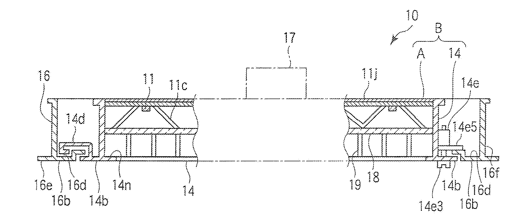
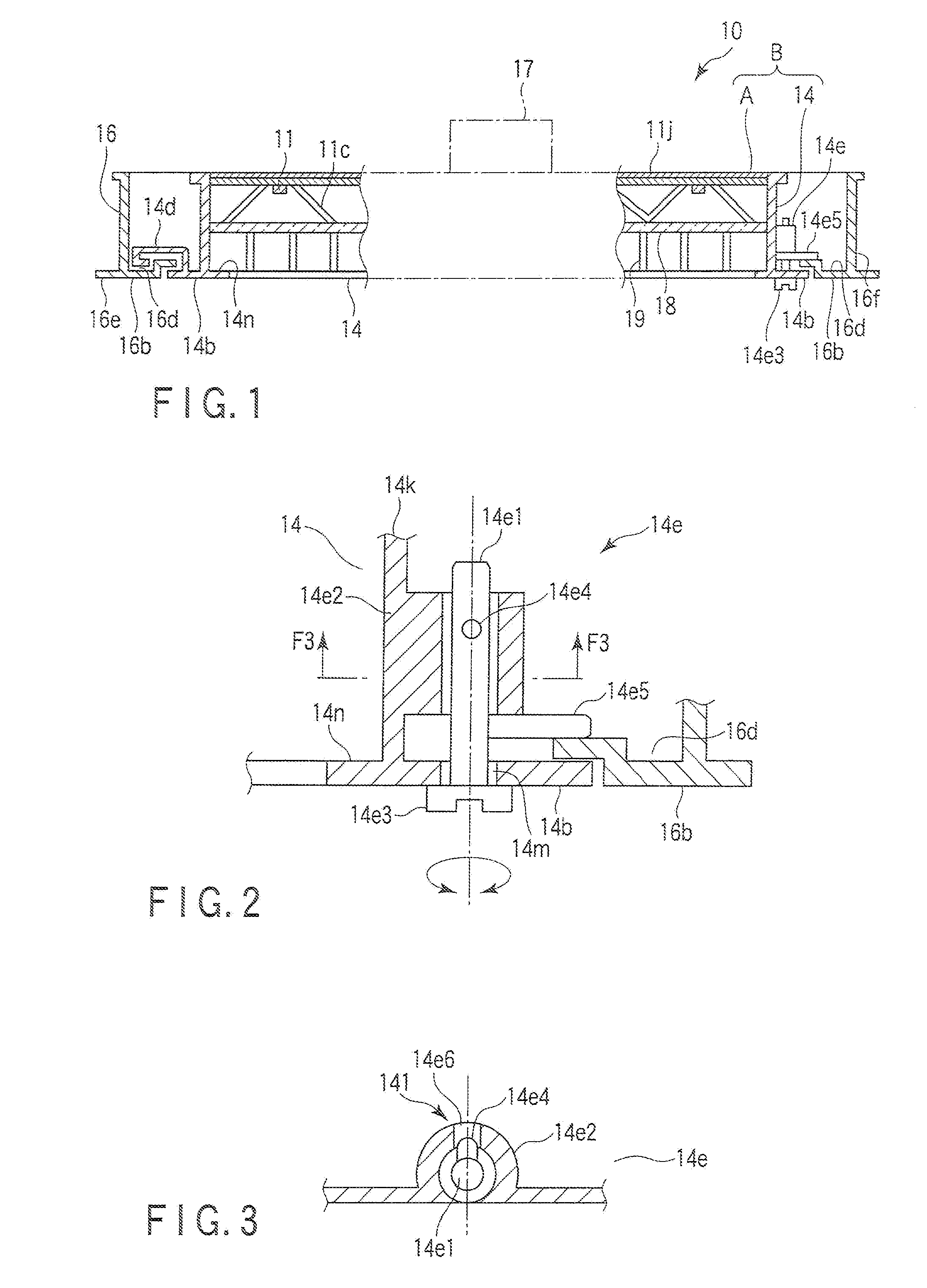
[0095]A luminaire 10 is a recessed ceiling type made in the form of a flat square panel. As shown in FIG. 1, the luminaire 10 comprises an equipment main body B, a support frame 16, an engagement unit 14e, and a lighting unit 17. The equipment main body B comprises a light-emitting unit A, and a main body frame 14. The light-emitting unit A comprises light-emitting elements 11 forming a light-emitting unit. The main body frame 14 holds the light-emitting unit A on the inner periphery. The support frame 16 holds the main body frame 14 on the inner periphery, and pivotally supports one end portion of the main body frame 14. The engagement unit 14c engages the other end portion of the main body frame 14 with the support frame 16. The lighting unit 17 lights up the light-emitting elements 11.

[0096]The light-emitting element 11 comprises a light-emitting diode (LED), and a fluorescent su...

second embodiment

[0175]The luminaire 10 of the second embodiment comprises an equipment main body B, a support frame 16, an engagement unit 14c, and a lighting unit 17, as shown in FIG. 24. The equipment main body B comprises the above-described light-emitting unit A, and main body frame 14. The main body frame 14 holds the light-emitting unit A on the inner periphery. The support frame 16 places the main body frame 14 on the inner periphery, and supports one end portion of the main body frame 14 rotationally movable. The engagement unit 14c engages the other end portion of the main body frame 14 with the support frame 16. The lighting unit 17 lights up the light-emitting elements 11.

[0176]The main body frame 14 is made of metal with high heat conductivity, white painted aluminum in the second embodiment, and is formed in one piece with a square frame body 14a. The frame body 14a is sized to house the light-emitting unit A inside as shown in FIG. 24 and FIG. 27. The light-emitting unit A is fit in t...

third embodiment

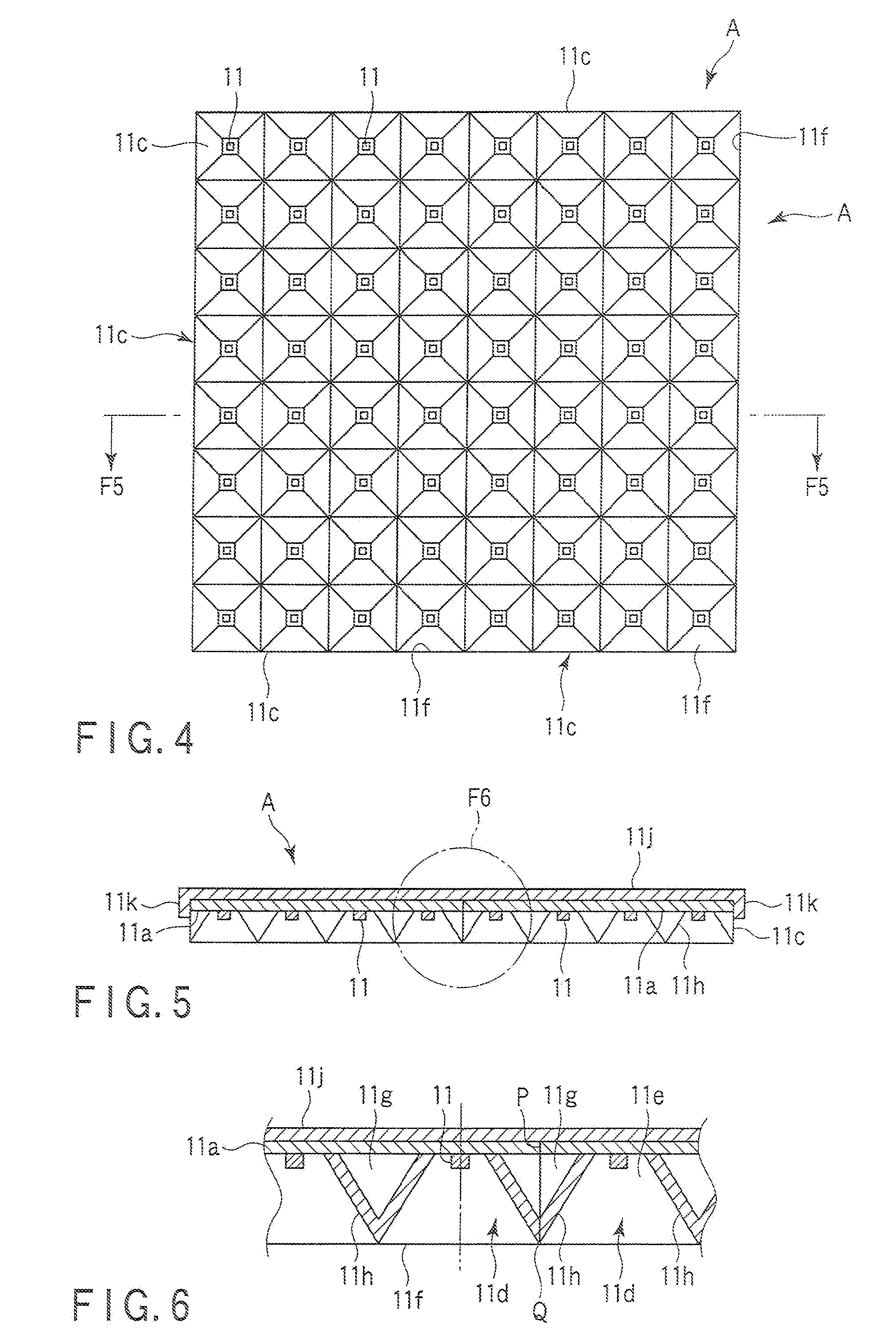
[0204]According to the luminaire 10 of the third embodiment, the reflector 11c is formed in one piece with a jointing piece 11g3 extending from one corner 11g1 to the base substrate 11a. The jointing piece 11ge3 is formed as a ¼-divided part of a cylinder. When four reflectors 11c1 are flatly arranged along the square base substrate 11a, they are placed so that the jointing pieces 11g3 oppose each other. The jointing piece 11g3 does not project outward from the outer peripheral side 11g2, so that the outer peripheral side 11g2 that is the periphery extending from the corner 11g1 provided with the jointing piece 11g3 tightly contact each other. As a result, the reflectors 11c are arranged along the base substrate 11a, and the reflector unit R is formed.

[0205]Adjacent reflectors 11c arranged so that the jointing pieces 11g3 contacts at the corner 11g1. Adjacent four jointing pieces 11g3 form one cylinder. Four reflectors 11c of the light-emitting unit A are tightly connected by the fa...


PUM


Abstract

A luminaire includes a light-emitting unit, a main body frame, a support frame, and a lighting unit. The light-emitting unit mounts light-emitting elements. The main body frame supports the light-emitting unit, and is formed rectangular having a hook-shaped engaging piece on one side. The support frame is formed rectangular surrounding the outer periphery of the main body frame, and has a groove-shaped receiving place to engage with the engaging piece of the main body frame, on one internal side. The lighting unit turns on the light-emitting elements.

Description

CROSS-REFERENCE TO RELATED APPLICATIONS[0001]This application is based upon and claims the benefit of priority from prior Japanese Patent Applications No. 2008-311217, filed Dec. 5, 2008; No. 2008-311418, filed Dec. 5, 2008; No. 2008-332886, filed Dec. 26, 2008; No. 2008-334065, filed Dec. 26, 2008; and No. 2008-334444, filed Dec. 26, 2008, the entire contents of all of which are incorporated herein by reference.BACKGROUND OF THE INVENTION[0002]1. Field of the Invention[0003]The present invention relates to a luminaire using a light-emitting element such as a light-emitting diode as a light source.[0004]2. Description of the Related Art[0005]A light-emitting diode has been increased in the light-emitting efficiency, and used as a light source. A lighting apparatus using a light-emitting diode as a light source has been commercialized as a relatively large lighting apparatus for home and office use. Jap. Pat. Applin. KOKAI Publication No. JP2008-257903 discloses a lighting apparatus ...

Claims


Application Information

Patent Timeline
IPC IPC(8): F21V1/00F21S4/00
CPCF21S8/026F21V7/0083F21Y2101/02F21V17/107F21V21/049F21Y2105/001F21Y2105/10F21Y2115/10
Inventor SUGISHITA, NAOKITAKAI, HOMAREOISHI, TAKAFUMIISHII, YASUHIKOHIEDA, MASANAOHASHIMOTO, YUTAKA
Owner TOSHIBA LIGHTING & TECH CORP
Why Eureka
Try Eureka