Cutting Tool Having Releasably Mounted Self-Clamping Cutting Head

a cutting head and mounting plate technology, which is applied in the direction of manufacturing tools, wrenches, wood boring tools, etc., can solve the problems of inconvenient installation, long set up time, and inaccuracy in positioning the non-ground flat surface relative to the grinding wheel

Active Publication Date: 2010-06-10
ISCAR LTD
View PDF10 Cites 52 Cited by
  • Summary
  • Abstract
  • Description
  • Claims
  • Application Information

AI Technical Summary

Benefits of technology

[0006]According to embodiments of the present invention there is provided a cutting tool having an axis of rotation around which the cutting tool rotates in a direction of rotation. The cutting tool comprises a tool shank and a replaceable self-clamping cutting head resiliently secured to the tool shank at a tool shank forward end by an interference fit between a male fixation member of the cutting head and a female fixation member of the tool shank. The male and female fixation members are each configured to have abutment regions, the abutment regions on the two fixation members mutually abutting one another. The male fixation member has a resilience slit, and in each cross section of the cutting tool taken perpendicular to the axis of rotation through mutual abutment regions between the male and female fixation members the cross sectional profiles of the mutual abutment regions are mutual arcuate sectors.

Problems solved by technology

Between the two grinding operations, the insert portion has to be rotated by 180° in order to present the non-ground flat surface to the grinding wheel, which may introduce an inaccuracy in the positioning of the non-ground flat surface relative to the grinding wheel.
The requirement of a clamp fixing screw introduces an extra complication and longer set up time when securing the replaceable tool head to the tool shank.

Method used


Image

  • Cutting Tool Having Releasably Mounted Self-Clamping Cutting Head
  • Cutting Tool Having Releasably Mounted Self-Clamping Cutting Head
  • Cutting Tool Having Releasably Mounted Self-Clamping Cutting Head

Examples


Embodiment Construction

[0026]In the following description, various aspects of the present invention will be described. For purposes of explanation, specific configurations and details are set forth in order to provide a thorough understanding of the present invention. However, it will also be apparent to one skilled in the art that the present invention may be practiced without the specific details presented herein. Furthermore, well-known features may be omitted or simplified in order not to obscure the present invention.

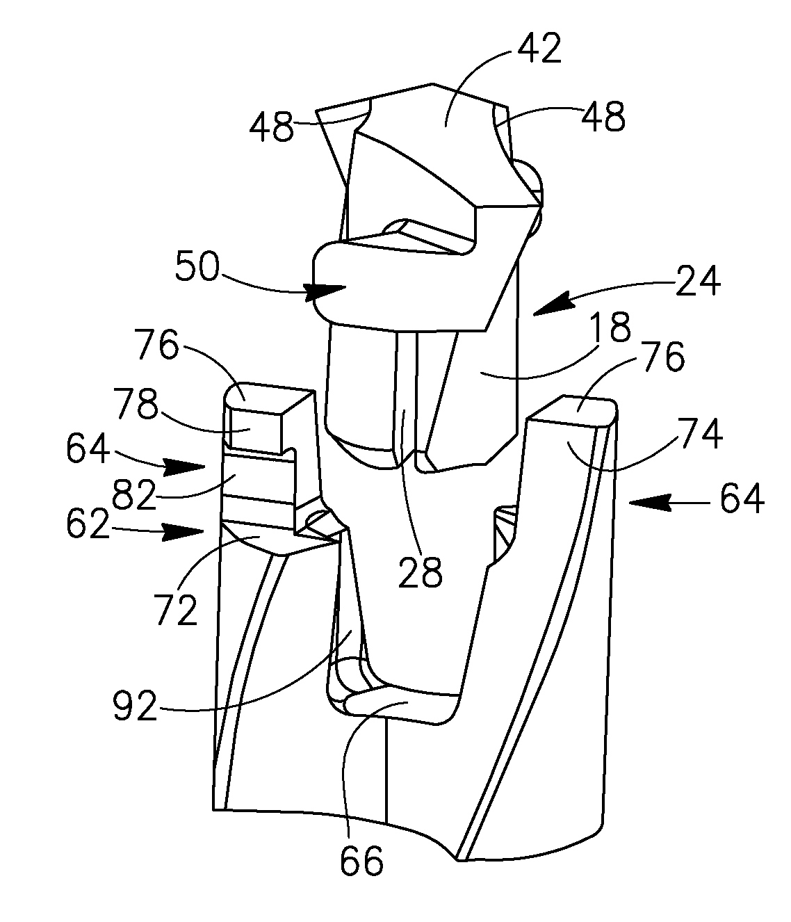
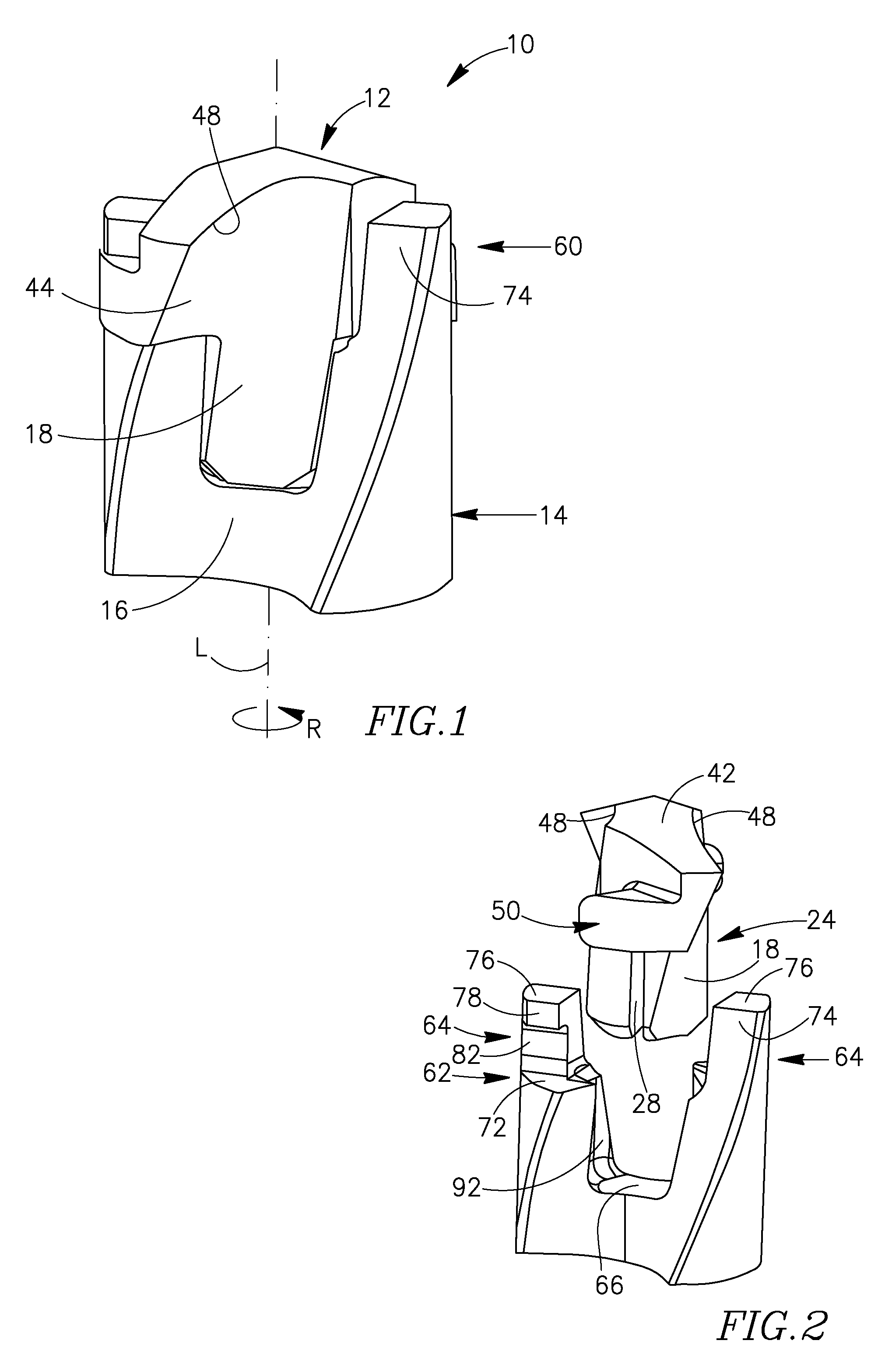
[0027]Reference is made to FIG. 1 showing a cutting tool 10 in accordance with embodiments of the present invention. The cutting tool 10 may be a drill, or any other kind of rotary cutting tool. The cutting tool 10 includes a cutting head 12 releasably mounted in a self-clamping manner on a tool shank 14 with the cutting head 12 and the tool shank 14 having a common axis of rotation L around which the cutting tool 10 rotates in a direction of rotation R. The cutting head 12 may be of the...


PUM

PropertyMeasurementUnit
axis of rotationaaaaaaaaaa
resilienceaaaaaaaaaa
elastic forceaaaaaaaaaa

Abstract

A cutting tool has a tool shank and a replaceable cutting head resiliently secured to the tool shank by an interference fit between a male fixation member of the cutting head and a female fixation member of the tool shank. The male fixation member has a resilience slit. In each cross section of the cutting tool taken perpendicular to an axis of rotation of the cutting tool through mutual abutment regions, the cross sectional profiles of the mutual abutment regions are arcuate sectors.

Description

FIELD OF THE INVENTION[0001]The current invention relates to a cutting tool having a releasably mounted cutting head.BACKGROUND OF THE INVENTION[0002]A drill having a releasably mounted cutting head is disclosed in U.S. Pat. No. 5,228,812. In a first embodiment disclosed in U.S. Pat. No. 5,228,812 the drill has an insert portion for cutting a workpiece and a shank portion, the insert portion being separably mechanically connected to the shank portion. The insert and shank portions have mutually engaging portions forming the connection between the insert and the shank, and a slit formed in either the insert or shank engaging portion. The insert portion and the shank portion are connected with each other using an elastic force which is caused by an elastic deformation upon mutual movement of the opposite surfaces of the slit in an engaging state of both portions, whereby the insert portion may be connected with or fixed to the shank portion by press-fitting the insert portion into the...

Claims


Application Information

Patent Timeline
Patent Type & Authority Applications(United States)
IPC IPC(8): B23B51/02
CPCB23B51/02B23B2251/02Y10T408/892Y10S408/713Y10T408/9095Y10T408/9097Y10T408/9098Y10T408/907B23B51/0003B23B2222/28
Inventor HECHT
Owner ISCAR LTD
Why Eureka
Try Eureka