
Loader Work Machine

Active Publication Date: 2010-06-10
KUBOTA LTD
View PDF6 Cites 13 Cited by
  • Summary
  • Abstract
  • Description
  • Claims
  • Application Information

AI Technical Summary

Benefits of technology

[0015]The present invention has been made in view of the above-described drawback and an object of the invention is to enable prevention of impairment of rear visibility by the hood during a work or the like, thus allowing a work by the loader work machine to be carried out smoothly.
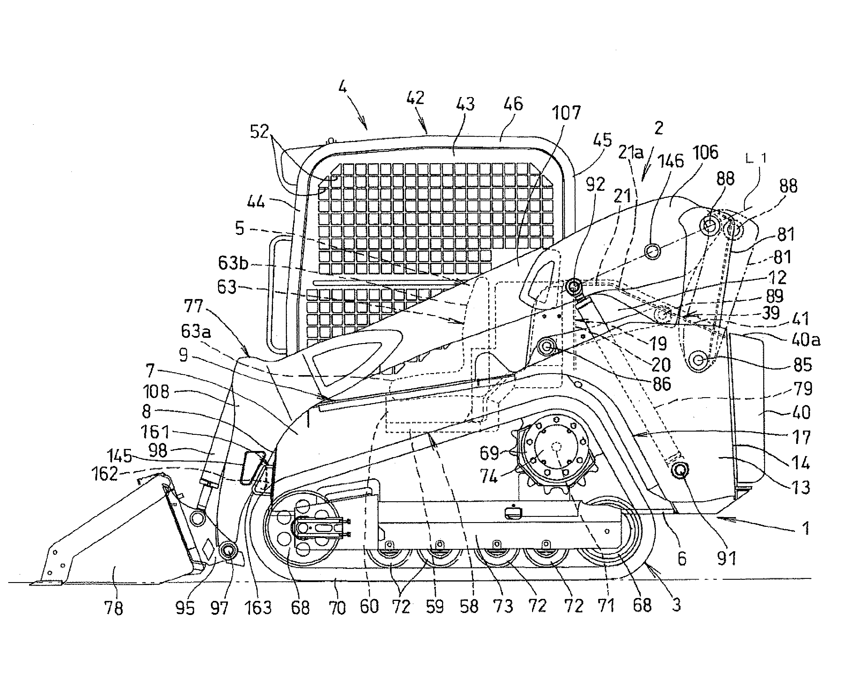
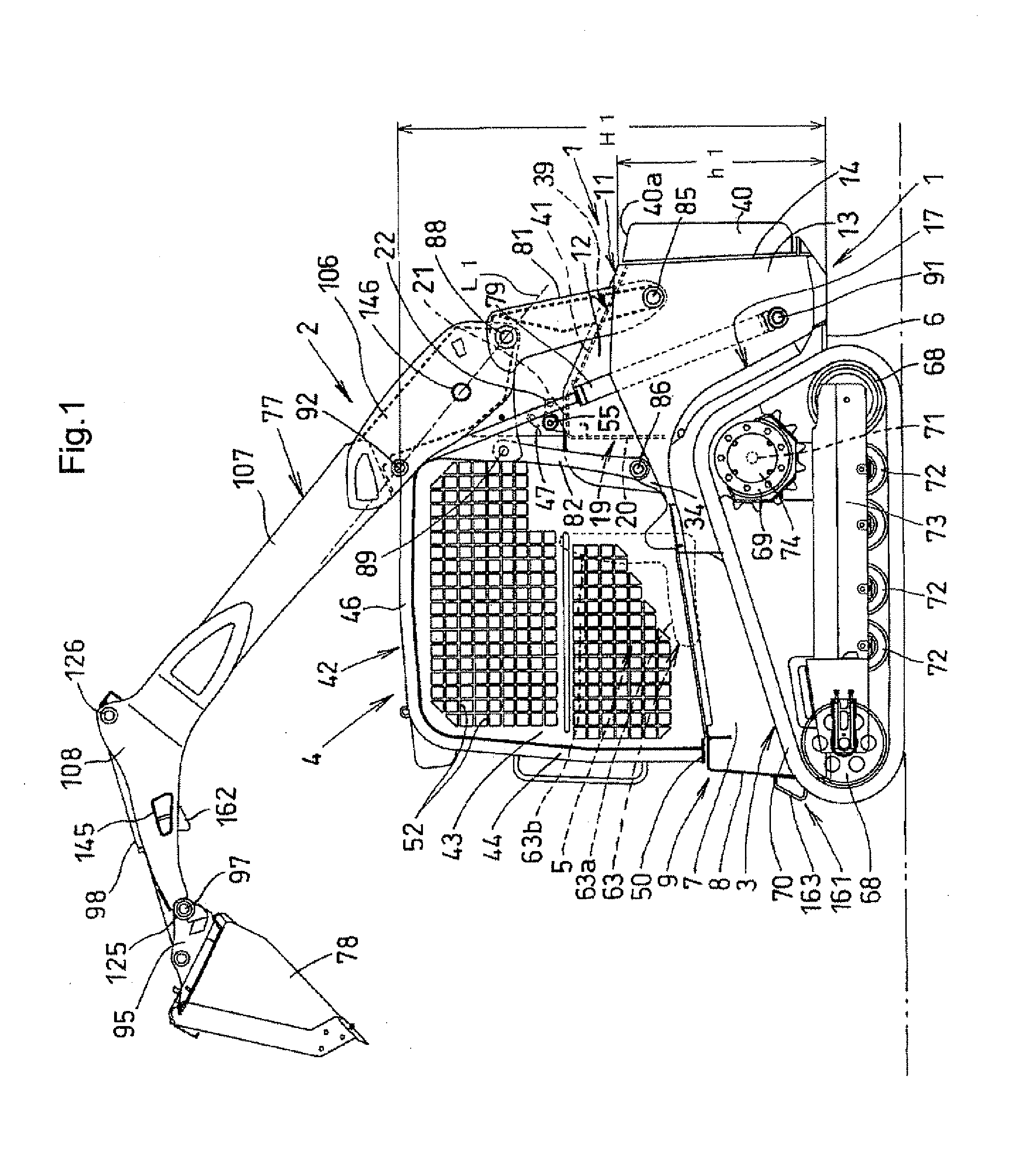
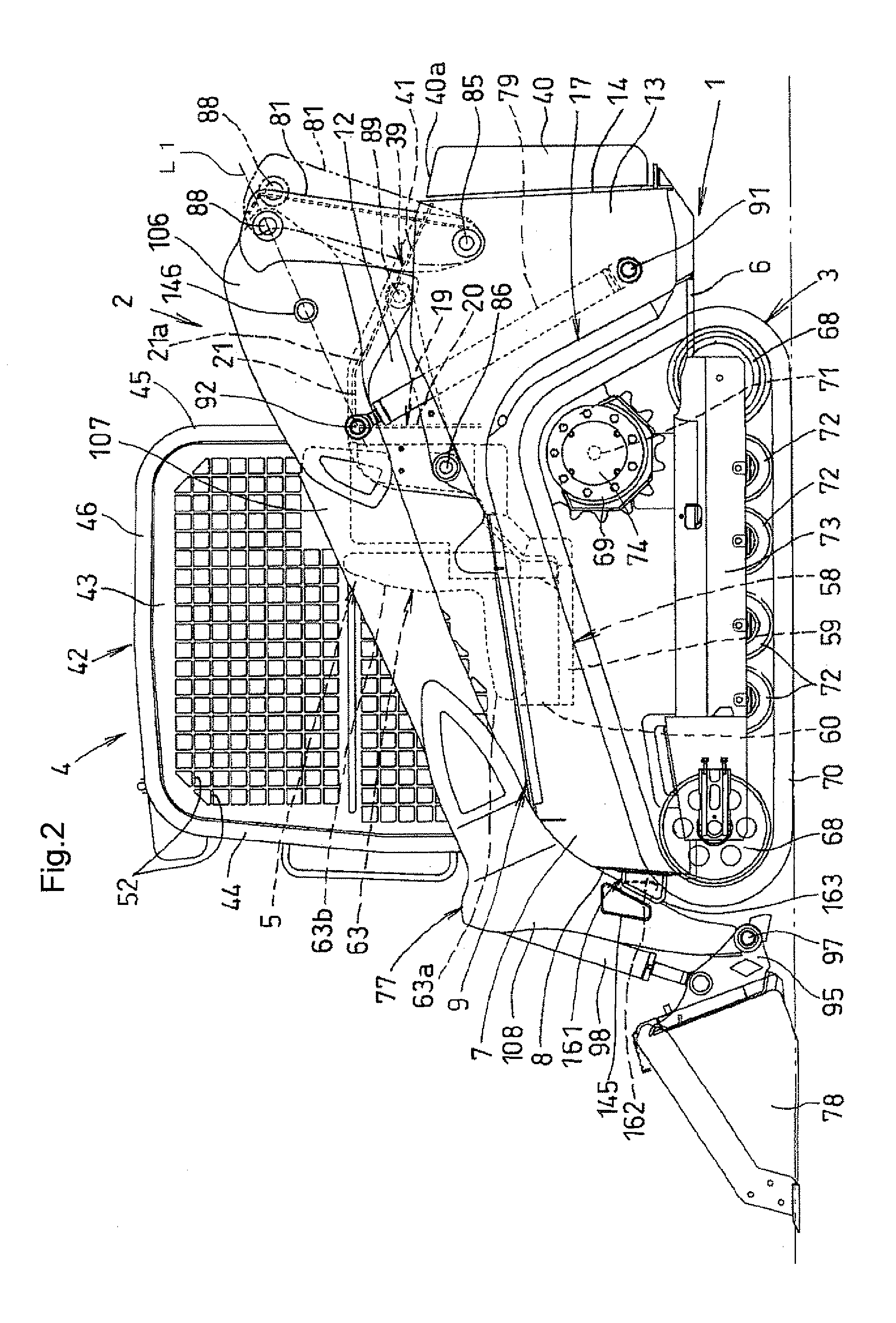
[0084]According to the present invention, the upper wall plate of the transverse connecting member, whose lower portion constitutes a hood for housing an engine, is disposed more downwardly than the vertical center of the cabin. The rear portion of the upper wall plate is inclined downwardly rearward. The hood upper wall is provided for covering a rear upper side between the pair of right / left support frame members. The front end portion of the hood upper wall is connected to a rear portion of the upper wall plate of the transverse connecting member. And, the hood upper wall is inclined downwardly rearward in correspondence with the rear portion of the upper wall plate. With these, in comparison with the height of the entire cabin, the height of the entire hood disposed rearwardly of the cabin can be restricted or remain low, so that the hood hardly interferes with the rear view. Therefore, during a work, a worker can see, from inside the cabin, also the rear lower side of the hood, so that the work by the loader work machine can be effected more smoothly.

Problems solved by technology

Thus, there is high risk of the rear link hitting an object present rearwardly of the loader work machine during work, thus interfering with the work.
For this reason, the rear visibility for the worker present inside the cabin was poor, so the work by the loader work machine would sometimes be difficult.

Method used


Image

  • Loader Work Machine
  • Loader Work Machine
  • Loader Work Machine

Examples


Embodiment Construction

[0108]Next, embodiments of a loader work machine implementing the present invention will be described with reference to the accompanying drawings. In FIG. 1 and FIG. 2, a track loader as a loader work machine relating to the present invention includes a machine body frame 1, a loader implement (excavating implement) 2 mounted on the machine body frame 1, and a pair of right / left traveling devices 3 supporting the machine body frame 1. Upwardly of the machine body frame 1, there is provided a driving section 5 having a driver's seat 63 to be described later, a steering lever, etc. On a front portion of the machine body frame 1, there is mounted a cabin (driver protecting device) 4 surrounding the driving section 5.

[0109]In FIGS. 3-7, the machine body frame 1 formed of iron plates etc. includes a frame body 9 and a pair of right support frame members 11. The pair of right / left support frame members 11 are connected to each other at the rear ends thereof by means of welding. The frame ...


PUM


Abstract

An improvement of a loader work machine is disclosed. A machine body frame includes a frame body having a bottom wall and a pair or right / left side walls, and a pair of right / left support frame members connected to a rear end of the frame body. A cabin is mounted on the machine body frame. A transverse connecting member is disposed rearwardly of the cabin for connecting the pair of right / left support frame members to right / left sides thereof, respectively. A pair of right / left arms are disposed on right / left sides of the machine body frame, with base portions thereof being vertically pivotally supported to the pair of right / left support frame members, respectively. A pair of right / left arm cylinders are provided between the base portions of the arms and the rear portions of the machine body frame for lifting up / down the arms. A hood is provided at the rear end of the frame body and downwardly of the transverse connecting member between the pair of right / left support frame members, for housing an engine. The transverse connecting member includes a front wall plate and an upper wall plate projecting rearward from an upper end of the front wall plate. The upper wall plate of the transverse connecting member is disposed more downwardly than the vertical center of the cabin. A rear portion of the upper wall plate is inclined downwardly rearward. A hood upper wall is provided for covering a rear upper side between the pair of right / left support frame members. A front end portion of the hood upper wall is connected to the rear portion of the upper wall plate of the transverse connecting member. The hood upper wall is inclined downwardly rearward in correspondence with the rear portion of the upper wall plate.

Description

TECHNICAL FIELD[0001]The present invention relates to a loader work machine.BACKGROUND ART[0002]Conventionally, there is known a loader work machine as under (see Patent Document 1):—[0003]A loader work machine comprising:[0004]a pair of right / left arms disposed on right / left sides of a machine body frame, with base portions thereof being vertically pivotally supported to rear portions of the machine body for allowing leading ends of the pair of right / left arms to be lifted up / down on the forward side of the machine body frame;[0005]a pair of right / left arm cylinders provided between the base portions of the arms and the rear portions of the machine body frame for lifting up / down the aims;[0006]a cabin mounted on the machine body frame;[0007]the machine body frame including a frame body having a bottom wall and a pair of right / left side walls, and a pair of right / left support frame members connected to a rear end of the frame body;[0008]base portions of the pair of right / left arms b...

Claims


Application Information

Patent Timeline
IPC IPC(8): E02F3/28B62D21/00E02F9/16E02F3/36
CPCE02F3/3405E02F3/3414Y10S414/131E02F9/0816E02F9/2275E02F3/432
Inventor YASUDA, TOYOAKIFUJINO, MASANORITAKEMURA, TOSHIHIKONAKATA, YASUOMATSUBARA, YOSHITAKAUEDA, YOSHIHIROTAKANO, YUUKIKAWAI, YUSUKESUMIYOSHI, RYOHEIANAMI, HIROYUKIMURAMOTO, NAOYAMITSUI, KENJIKAWANO, YOUHEIIKUMURA, TAKESHI
Owner KUBOTA LTD
Learn More