

Hysteretic LED driver with low end linearization
- Summary
- Abstract
- Description
- Claims
- Application Information
AI Technical Summary
Benefits of technology
Problems solved by technology
Method used
Image

Examples
Embodiment Construction
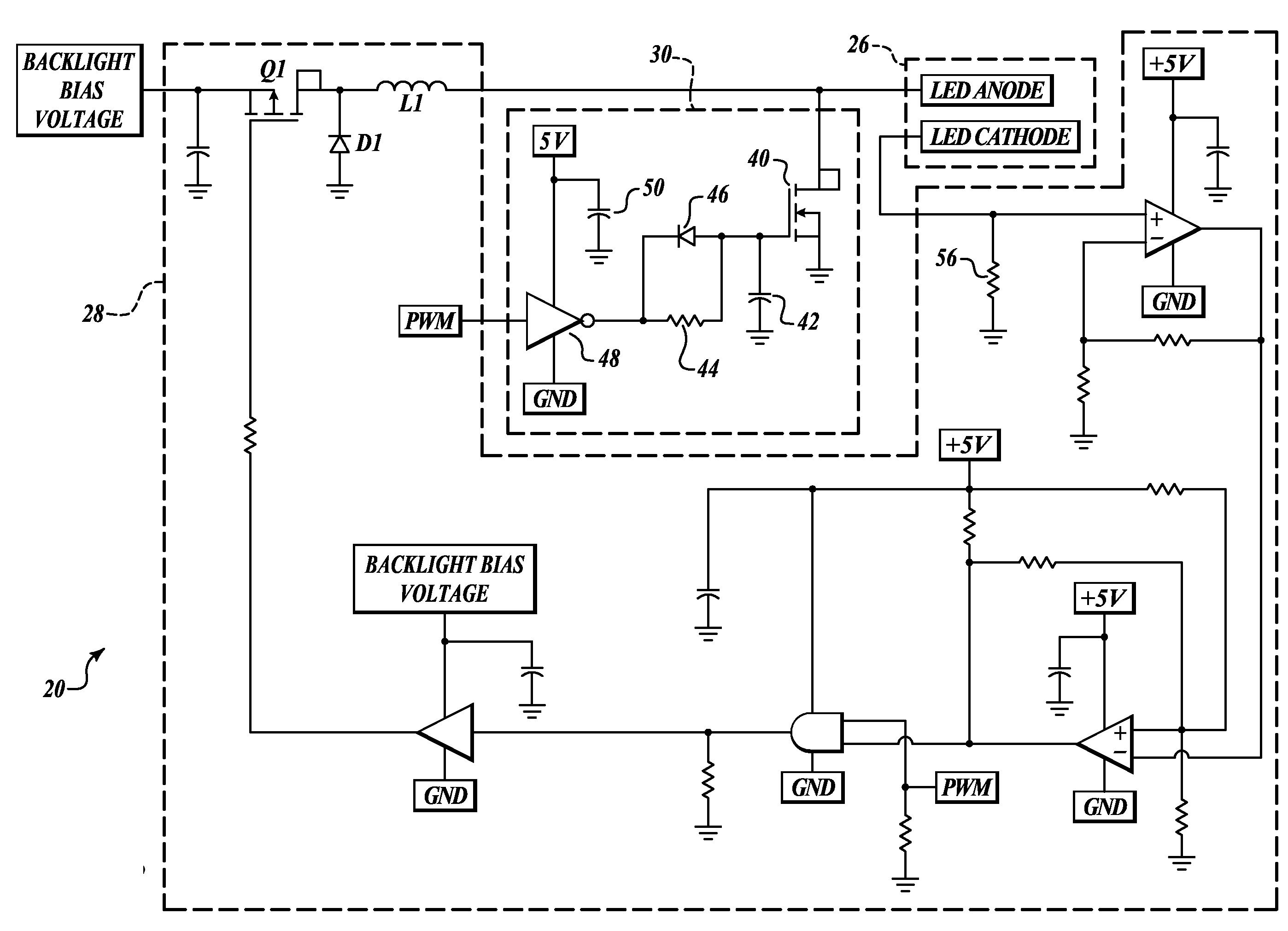
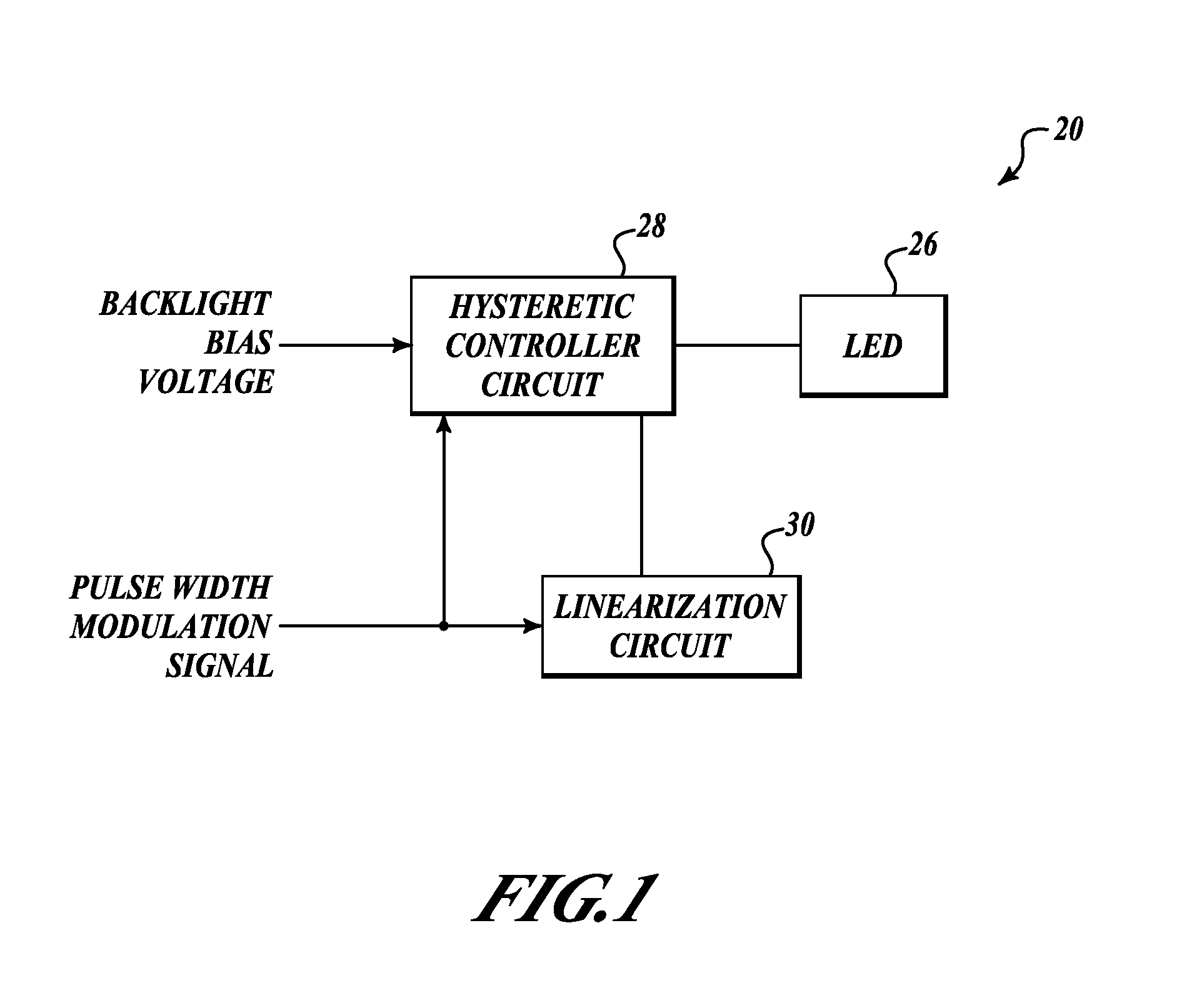
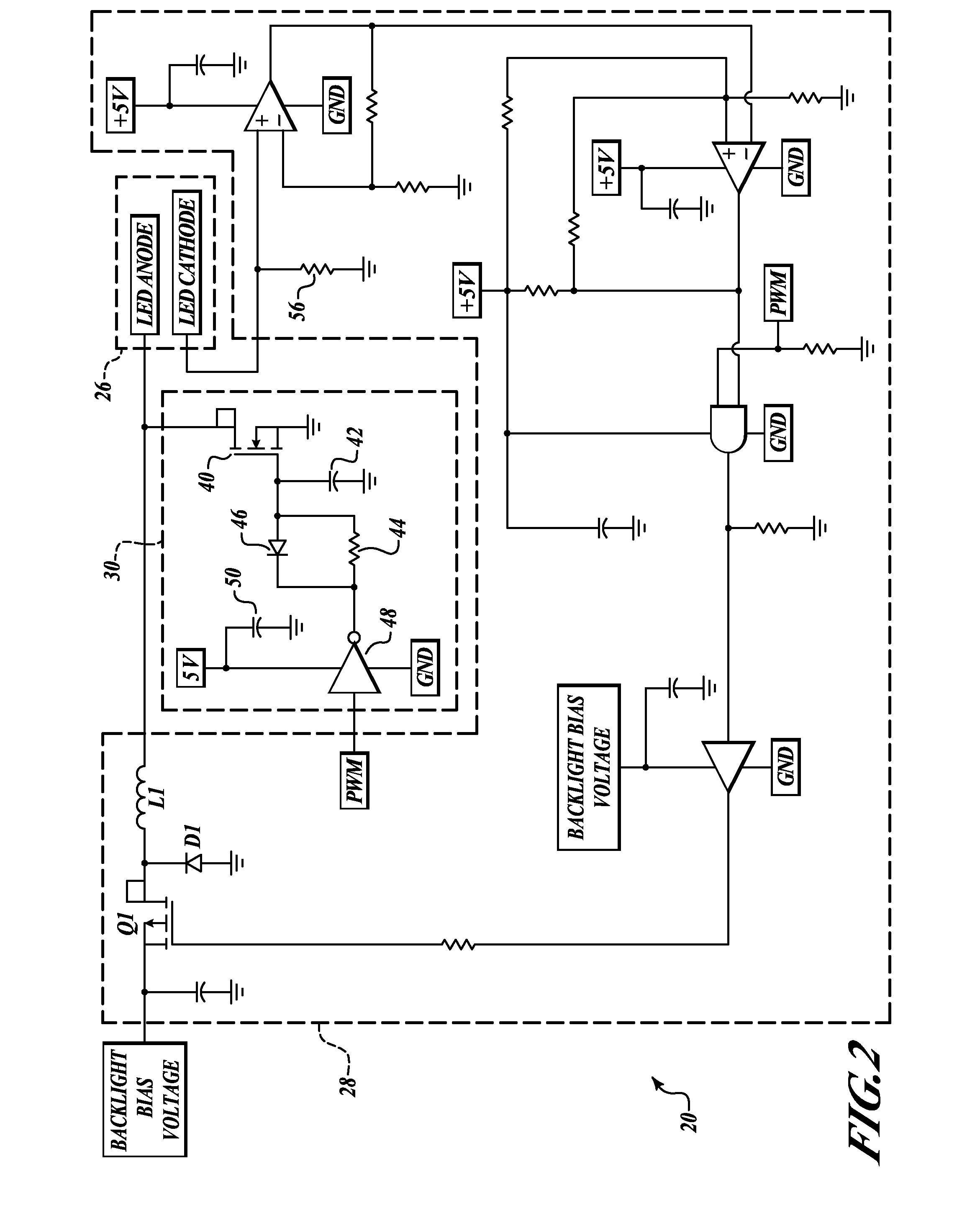
[0011]FIG. 1 illustrates a block diagram of an example circuit 20 for hysteretically driving one or more Light Emitting Diodes (LEDs) 26 while employing low-end linearization. The circuit 20 includes a hysteretic controller circuit 28 that controls the current to one or more LEDs 26 according a received Pulse Width Modulation (PWM) signal and a backlight bias voltage (VIN). The backlight bias voltage is preferably controlled by a user operating a switch, which allows the user to set a dimming value for the LEDs 26 with the PWM signal. An example of the hysteretic controller circuit 28 is described in U.S. patent application Ser. No. 11 / 069,298, filed Mar. 1, 2005 and Ser. No. 11 / 181,815 filed Jul. 15, 2005, the contents of which are hereby incorporated by reference.
[0012] The circuit 20 also includes a linearization circuit 30 that provides better control of the brightness level especially at low luminance values. The linearization circuit 30 operates in accordance with the receive...
PUM
 Abstract
Description
Claims
Application Information