
Internal combustion engine having variable compression ratio selection as a function of projected engine speed

Inactive Publication Date: 2007-05-03
FORD GLOBAL TECH LLC
View PDF7 Cites 3 Cited by
  • Summary
  • Abstract
  • Description
  • Claims
  • Application Information

AI Technical Summary

Benefits of technology

[0011] In one embodiment, to reduce the effect of signal noise generation which may result from using the derivative of engine speed, depending on the engine inertia or rate of throttle manipulation, the system includes a filter for filtering engine speed derivative, for example, with a software filter. With such filtering, smooth engine speed trends can be obtained (again, positive indicating engine speed increment and negative indicating engine speed reduction without too much of signal noise.

Problems solved by technology

Unfortunately, compression ratios are limited by the availability of high-octane fuels needed to prevent combustion detonation or knock at high engine loads, and therefore a compression ratio is selected to operate on available fuels, and avoid knock.
However, drivability and engine knock issues may occur by changing engine compression ratio while driving a vehicle in different environmental conditions.
The problem is how to take into account those factors so as to select appropriate engine compression ratio to obtain optimum fuel economy without sacrificing drivability.
More particularly, the CR change is only possible either at intake or exhaust stroke.
However, as the engine speed increases, the time that a cylinder stays on either intake or exhaust stroke gets smaller, explaining why the VCR mechanism is not capable of switching from one CR to the other CR at higher engine speed.
When the VCR engine loses an opportunity to switch to low compression mode at a higher engine speed, it may result in severe engine knock at higher engine load and speed, possibly resulting in engine damage.

Method used


Image

  • Internal combustion engine having variable compression ratio selection as a function of projected engine speed
  • Internal combustion engine having variable compression ratio selection as a function of projected engine speed
  • Internal combustion engine having variable compression ratio selection as a function of projected engine speed

Examples


Embodiment Construction

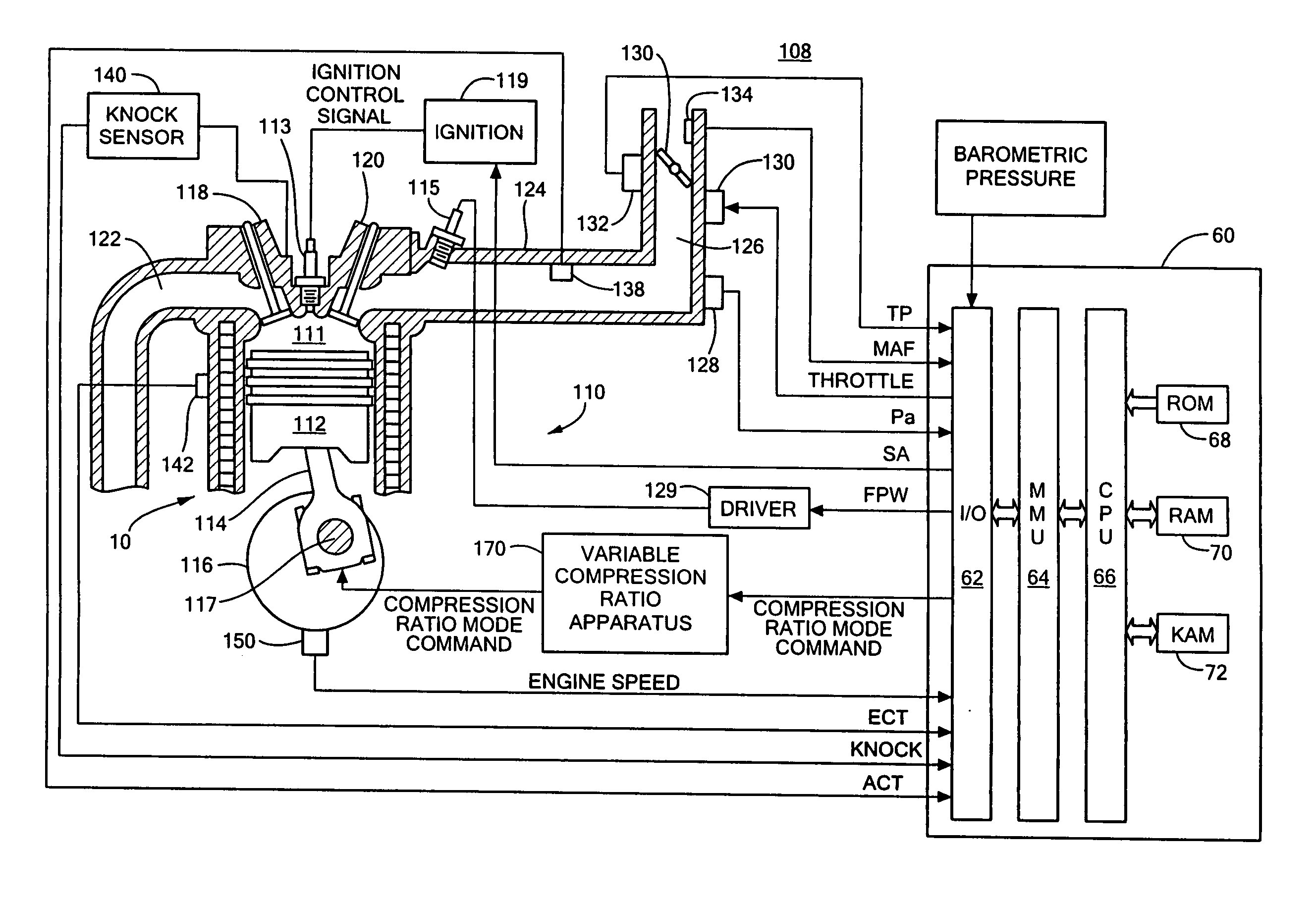
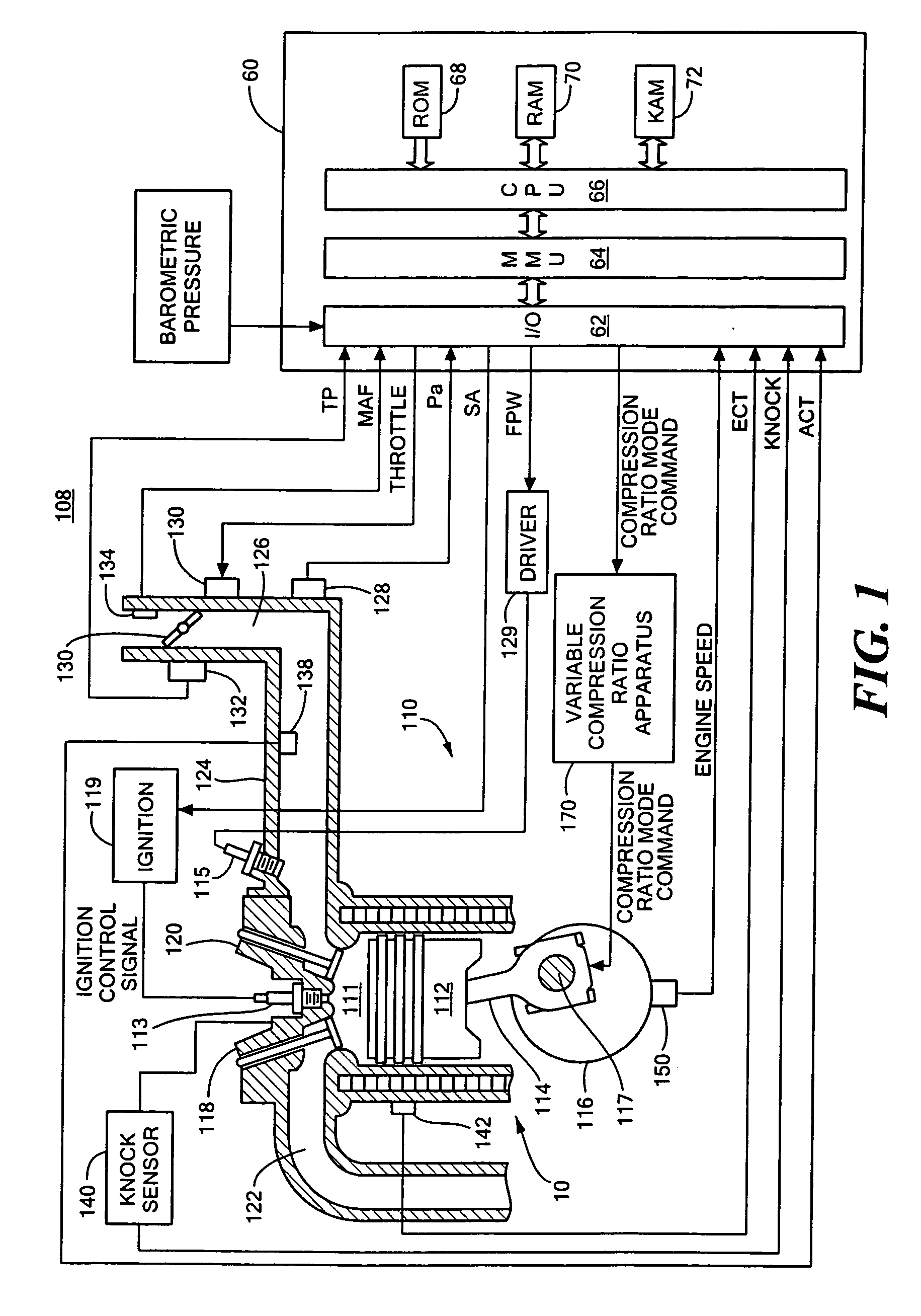
[0019]FIG. 1 shows an exemplary variable compression ratio internal combustion engine 10 in accordance with the present invention. As will be appreciated by those of ordinary skill in the art, the present invention is independent of the particular underlying engine configuration and component designs, and as such can be used with a variety of different internal combustion engines having more than one compression ratio operating modes. The engine, for example, can be constructed and arranged as a discrete compression ratio engine operating for example at a high compression or at low compression, or as a continuously variable compression ratio engine capable of operating at an infinite number of discrete compression ratios. Similarly, the present invention is not limited to any particular type of apparatus or method required for varying the compression ratio of the internal combustion engine.

[0020] Referring again to FIG. 1, the engine 110 includes a plurality of cylinders (only one ...


PUM


Abstract

A method for operating an internal combustion engine. The method includes: providing a functional relationship between time rate of change in engine speed, and compression ratio switching engine speed limit; determining time rate of change in engine speed; determining from the determined rate of change of engine speed and the function whether the engine speed exceeds the compression ratio switching engine speed; and commanding the engine to operate at a relatively low compression ratio if the determined time of change in engine speed exceeds the compression ratio switching engine speed limit and commanding the engine to operate at a relatively high compression ratio if the determined time of change in engine speed is less than the compression ratio switching engine speed limit.

Description

TECHNICAL FIELD [0001] This invention relates generally to variable compression ratio internal compression engines. BACKGROUND AND SUMMARY [0002] As is known in the art, the “compression ratio” of an internal combustion engine is defined as the ratio of the cylinder volume when the piston is at bottom-dead-center (BDC) to the cylinder volume when the piston is at top-dead-center (TDC)—generally, the higher the compression ratio, the higher the thermal efficiency and fuel economy of the internal combustion engine. Unfortunately, compression ratios are limited by the availability of high-octane fuels needed to prevent combustion detonation or knock at high engine loads, and therefore a compression ratio is selected to operate on available fuels, and avoid knock. So-called “variable compression ratio” internal combustion engines have been developed, for example, having higher compression ratios during low load conditions and lower compression ratios during high load conditions. [0003] ...

Claims


Application Information

Patent Timeline
IPC IPC(8): F02B75/04B60T7/12F02B75/02F02D41/00G06F17/00
CPCF02B75/04F02D15/02F02D41/107F02D2200/1012
Inventor GLUGLA, CHRIS P.TRUMPY, DAVID K.YOO, IN KWANG
Owner FORD GLOBAL TECH LLC
Learn More