Cast-in channel

a technology of casting channel and anchoring member, which is applied in the direction of structural elements, forms/shuttering/falseworks, and auxilary members of forms/shuttering/falseworks, etc., can solve the problems of screwing in the anchoring member over its entire length, requiring insertion and screwing, etc., and achieves advantageous load-carrying characteristics and reduce mounting space

Inactive Publication Date: 2010-06-17
HILTI AG
View PDF11 Cites 13 Cited by
  • Summary
  • Abstract
  • Description
  • Claims
  • Application Information

AI Technical Summary

Benefits of technology

[0009]The anchoring members are attached externally to the body of the channel with respect to the receiving space. Because of this, the anchoring members can also be attached to a channel body that has previously been provided with an infill. Advantageously, the rim hole pointing toward the interior of the receiving space has an internal thread adapted to threadedly receive an externally threaded anchoring member to fixedly attach the same to the channel body. It is not necessary for the shank to be externally threaded over its entire length. Advantageously, only the free end is provided with an externally threaded portion, which makes the entire cast-in channel easier and less expensive to manufacture. In addition, different types of anchoring members can be attached to the same type of channel body, which also allows the cast-in channel to be adapted to different load requirements at the construction site, if necessary. Even a previously assembled cast-in channel can be easily adapted to a different type of load, also directly at the construction site, for example. Yet, until the anchoring members are attached to the channel body, the cast-in channel occupies a minimum volume during shipping. In spite of the attachment point provided on the channel body, adjacent channel bodies will not be damaged by the attachment point during shipping.
[0011]Preferably, at least one depression which faces outwardly with respect to the receiving space is provided in the channel body, at least one of the rim holes being located in the depression. This depression, which may be cup-shaped, creates additional space, permitting the rim hole to be larger, without reducing the mounting space for the connecting element within the receiving space. If the rim hole has an internal thread for attachment of an anchoring member, it is thereby possible to provide a relatively greater number of thread turns. The greater grip length at the rim hole allows greater loads to be transferred to the base material, whereby the load-carrying capacity of the cast-in channel can be ensured while reducing the amount of material required to manufacture the same. In addition, by providing the depression, this portion of the channel body is work-hardened, so that the material of the channel body has a higher strength in this highly stressed region.
[0012]Preferably, the at least one depression has a bottom portion, and at least one of the rim holes is located in the bottom portion of the depression, which allows for simple manufacture of the channel body, and enables the loads to be transferred to the base material in an advantageous manner. Advantageously, the rim hole located in the bottom portion is oriented perpendicular to the bottom portion.
[0015]Preferably, the rim height of the at least one rim hole is no greater than the depth of the at least one depression, so that the free end of the rim hole will not reduce the mounting space for the connecting element within the receiving space.
[0016]Preferably, at least the bottom portion of the at least one depression is provided with reinforcing indentations, thereby advantageously strengthening this region of the depression and imparting advantageous load-carrying characteristics to the cast-in channel.
[0017]Preferably, the anchoring members are inseparably mounted in the rim holes. In this manner, the anchoring members are prevented from unintentional loosening once they are attached to the channel body. For example, an adhesive may be provided to captively secure the anchoring members to the channel body once they are attached, for example screwed thereto. In an alternative embodiment, the free end of the rim hole is rolled over and the anchoring members are screwed in at a predetermined maximum torque.

Problems solved by technology

The drawback of the known approach is that the anchoring members have to be inserted through the mounting opening and screwed in over their entire length.

Method used


Image

  • Cast-in channel
  • Cast-in channel
  • Cast-in channel

Examples


Embodiment Construction

[0023]In all of the figures, like parts have been given like reference numerals.

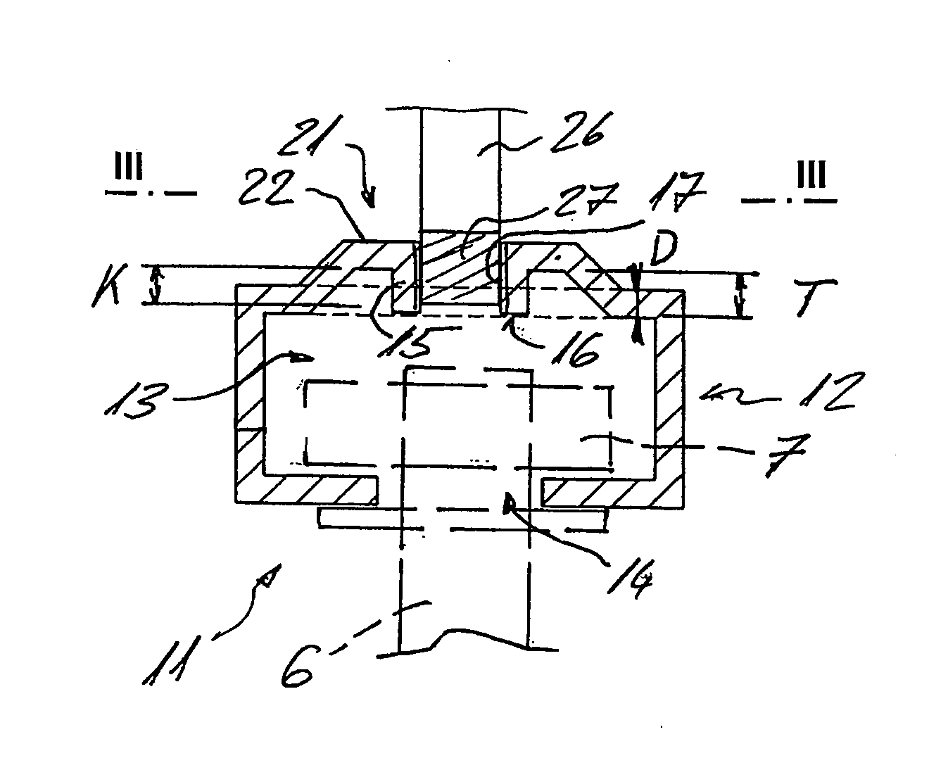
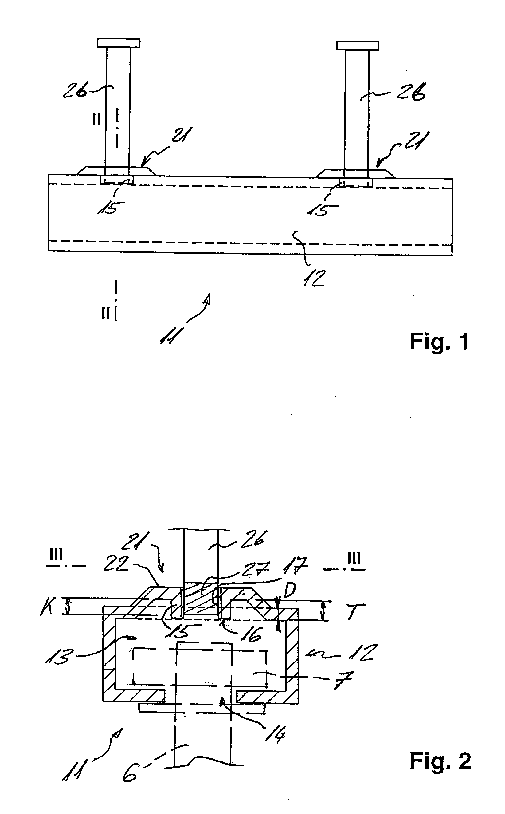
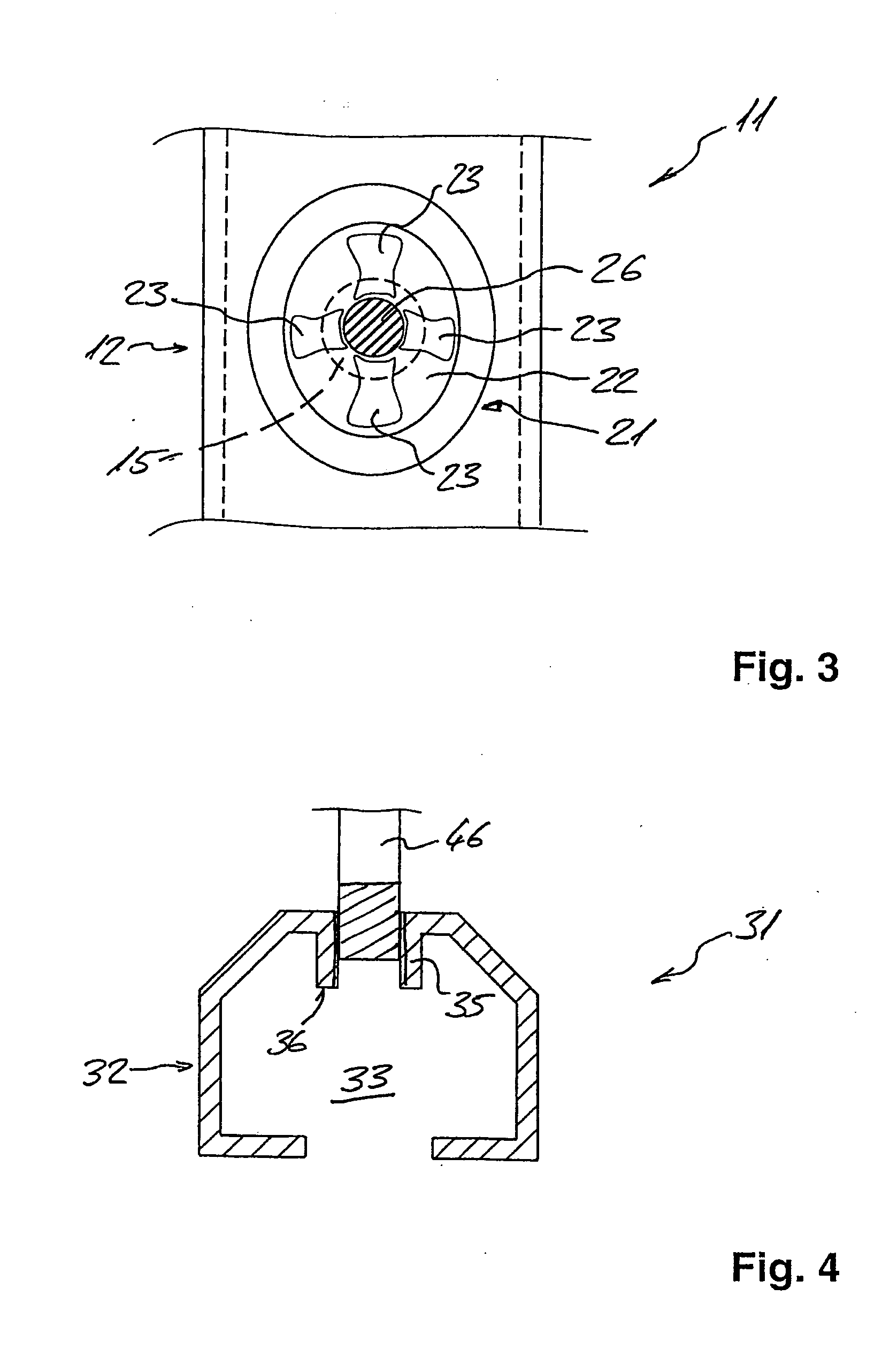
[0024]The cast-in channel 11 illustrated in FIGS. 1 through 3 has a channel body 12 and anchoring members 26 fixedly attached thereto. Channel body 12 forms a receiving space 13 for receiving a connecting element 7 used to fixedly attach a fastening element 6 to cast-in channel 11, receiving space 13 being accessible from the outside via a mounting opening 14 extending along the length dimension of channel body 12.

[0025]Channel body 12 is provided with two depressions 21 which face outwardly with respect to the receiving space 13 and which each have a bottom portion 22. Each bottom portion 22 is provided with a rim hole 15 having an internal thread 17 to allow attachment of anchoring members 26, the free end 16 of said rim hole pointing toward receiving space 13. Bottom portion 22 of depression 21 is non-concentric in cross section with respect to the rim hole 15 located therein. In addition, bottom port...


PUM


Abstract

The present invention relates to a cast-in channel having a channel body which forms a receiving space for receiving a connecting element used to fixedly attach a fastening element to the cast-in channel, the channel body further being provided with rim holes and with anchoring members which can be fixedly attached to the channel body by mounting them in the rim holes. The free ends of the rim holes point toward the receiving space.

Description

[0001]This claims the benefit of German Patent Application DE 10 2008 054 799.9, filed on Dec. 17, 2008 and hereby incorporated by reference herein.[0002]The present invention relates to a cast-in channel.BACKGROUND[0003]Cast-in channels of this type are used to provide flexible fixing points on a cast component, such as one of concrete. To this end, such cast-in channels are placed in the formwork prior to casting the component and incorporated therein during the casting process. Fastening elements can be fixedly attached to the cast-in channels using channel nuts, rear- engagement elements or T-head bolts as connecting elements, which are received in the receiving space within the channel body. The loads are transferred into the cured component via the channel geometry and the anchoring members.[0004]Cast-in channels whose anchoring members are permanently attached to the body of the channel, for example by welding, must be completely manufactured at the factory. Therefore, they t...

Claims


Application Information

Patent Timeline
Patent Type & Authority Applications(United States)
IPC IPC(8): E04B1/41E04G17/06
CPCE04B1/4107
Inventor HEUDORFER, MARKUSBASCHE, HOLGERGEBHARD, JUERGENBIRNBAUM, ULRICH
Owner HILTI AG
Why Eureka
Try Eureka