

Aircraft undercarriage with motorization and transmission
a technology of motorized and transmission transmission and aircraft, applied in the field of aircraft, can solve the problems of additional constraints in the design of the aircraft, and the number of constraints
- Summary
- Abstract
- Description
- Claims
- Application Information
AI Technical Summary
Benefits of technology
Problems solved by technology
Method used
Image

Examples
first embodiment
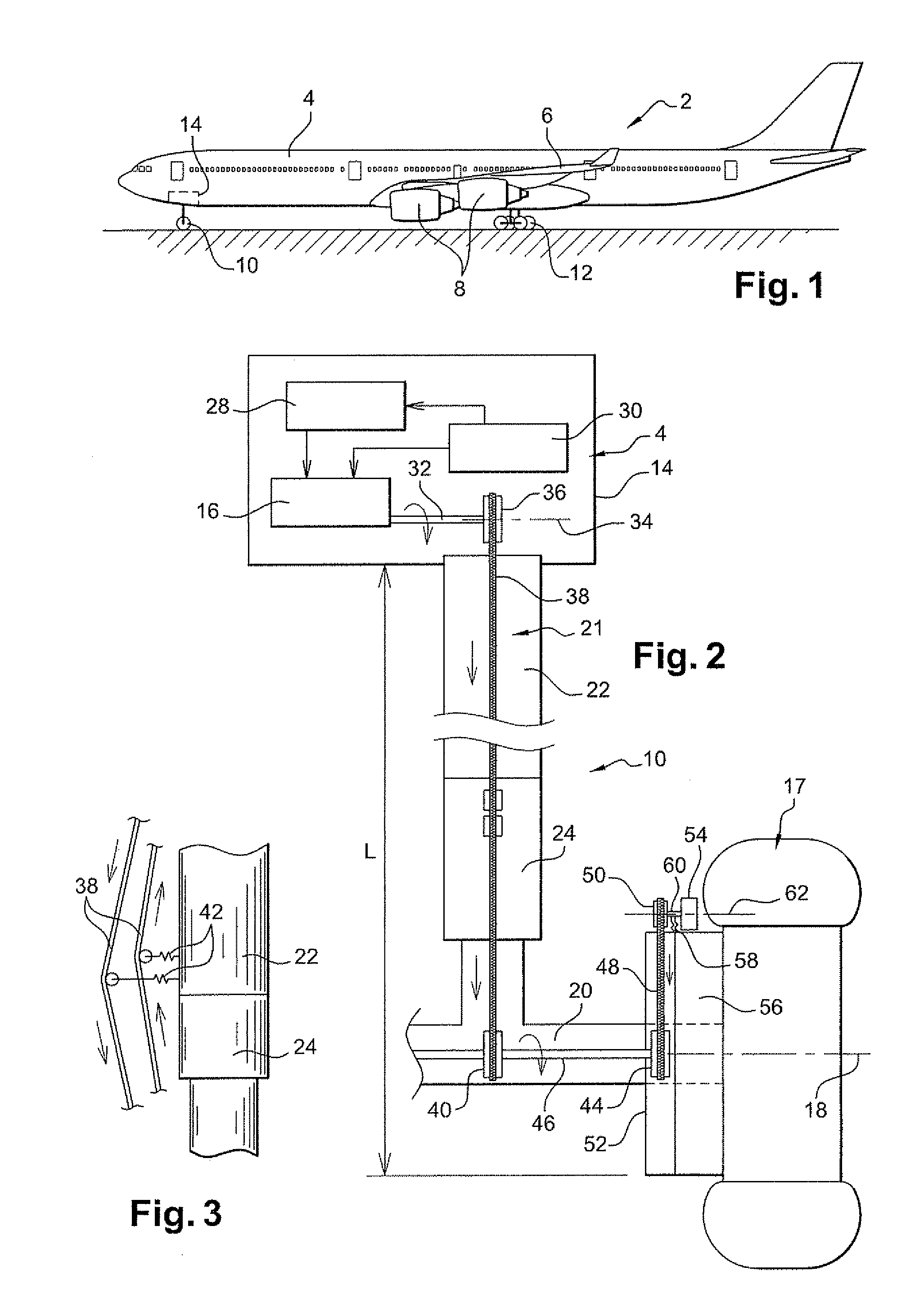
[0041]There follows a description with reference to FIGS. 1 to 3 of an aircraft of the invention. Specifically, the aircraft 2 is an airplane that takes off and lands by running along a runway. Nevertheless, the invention is equally applicable to other types of aircraft, in particular to vertical takeoff and landing aircraft.
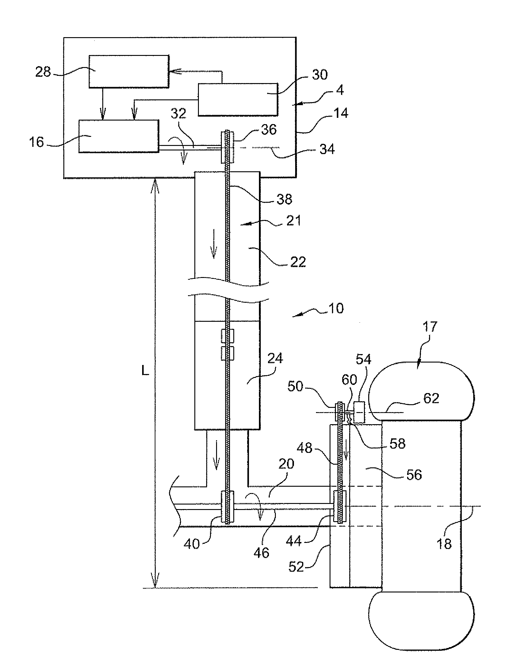
[0042]The aircraft 2 comprises a fuselage 4, two wings 6, and four engines 8. Each wing carries one pair of engines 8. In the present example, the aircraft has a nose undercarriage 10 and three main undercarriages referenced 12. One of the main undercarriages extends vertically under a middle portion of the fuselage and the other two main undercarriages extend vertically under respective one of the wings. The fuselage 4 includes a compartment 14 forming a well for receiving the nose undercarriage 10, which undercarriage may present a retracted position in which it is received completely within the well 14, and a deployed position in which it extends in the verti...
second embodiment
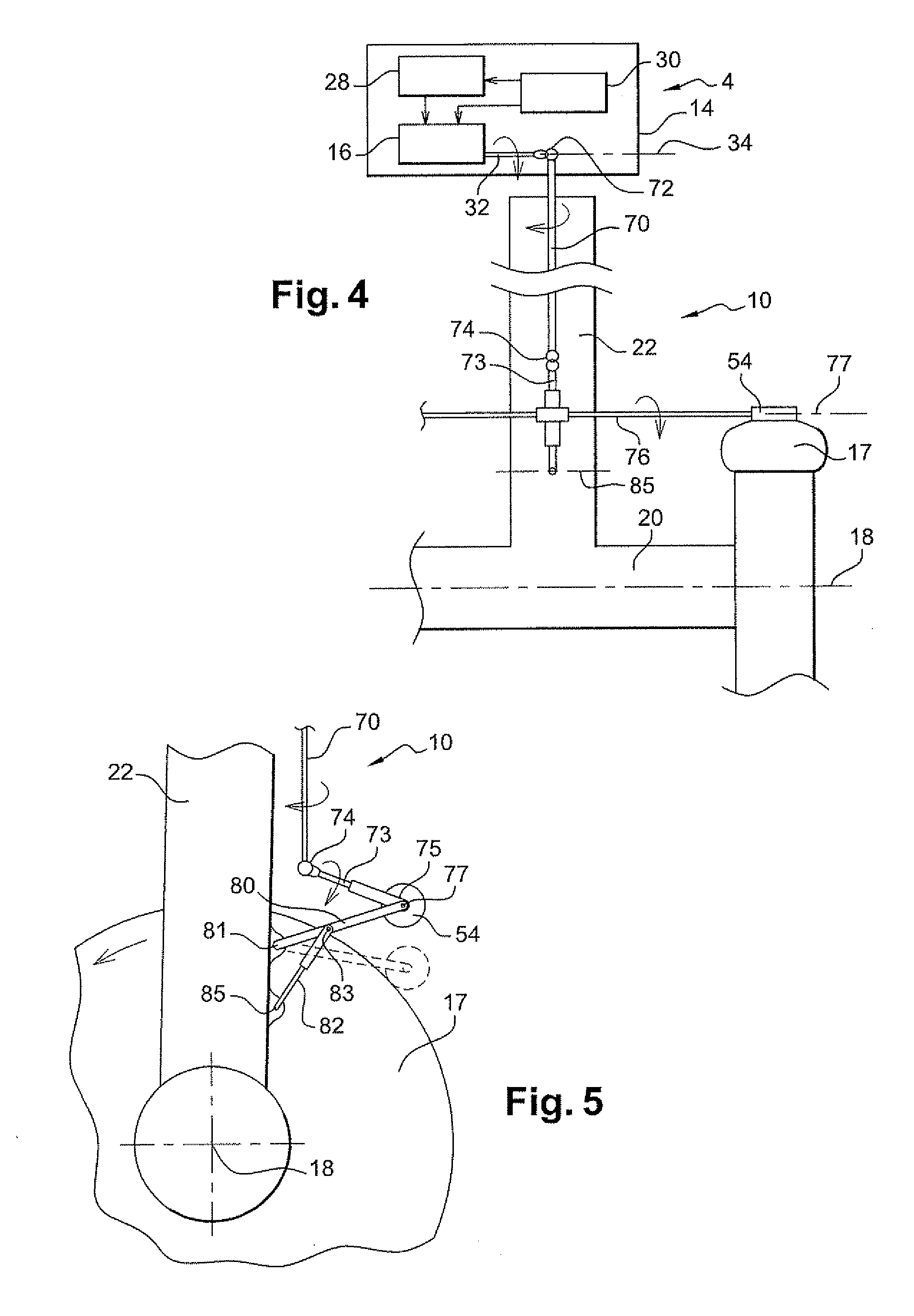
[0052]the invention is described below with reference to FIGS. 4 and 5.
[0053]Elements that are identical to those of the first embodiment are not described again. In particular, the shock absorber is not shown. In this embodiment, the mechanism for transmitting motion from the motor 16 to the wheel 17 comprises, instead of the chain 38, a shaft 70 extending vertically behind the leg 22 and parallel therewith. The shaft 70 is connected to the shaft 32 of the engine via one or more cardan joints 72.
[0054]The mechanism also includes an actuator 73, e.g. made in the form of a fluid-actuated jack. An upstream end of the actuator is connected to the shaft 70 by means of one or more cardan joints 74. The downstream end of the actuator 73 is connected to a rotary shaft 76 of horizontal axis 77 parallel to the axes 18 and 34, and having a downstream end, to the right in FIG. 4, that carries a friction roller 54. In this example, the roller is in friction engagement with the surface of the tr...
third embodiment
[0060]A third embodiment is shown in FIGS. 6 to 9. In this embodiment, the friction roller 54 is in contact, not with the surface of the tire tread, but with a lateral surface of the tire, e.g. on its inside 90, as shown to the left in FIG. 6. Under such circumstances, good contact can be guaranteed between the roller 54 and the tire by using a second roller or counter-roller 86 that is optionally active, and that bears on the side of the tire that is opposite from the side on which the roller 54 travels. In this example, the opposite side is the outside 92, on the right in FIG. 4.
[0061]The rollers 54 and 86 are thus in contact with opposite side walls of the tire. The rollers are carried by respective mutually parallel shafts 94 and they are constrained to rotate with their shafts. The shafts 94 are connected to each other by an actuator 96 that is pressure adjusted so that, at all times, the pressure exerted by the two rollers on the tire is constant and corresponds to the level n...
PUM
 Abstract
Description
Claims
Application Information