Current-balance circuit and backlight module having the same

a current balance circuit and backlight module technology, applied in the field of circuits, can solve the problems of generating output driving current errors, requiring a large amount of operational amplifier elements, and a higher cost of production, so as to improve the reliability of driving current and luminance, reduce extra power consumption, and improve the efficiency of backlight modules

Inactive Publication Date: 2010-06-17
CHUNGHWA PICTURE TUBES LTD
View PDF5 Cites 88 Cited by
  • Summary
  • Abstract
  • Description
  • Claims
  • Application Information

AI Technical Summary

Benefits of technology

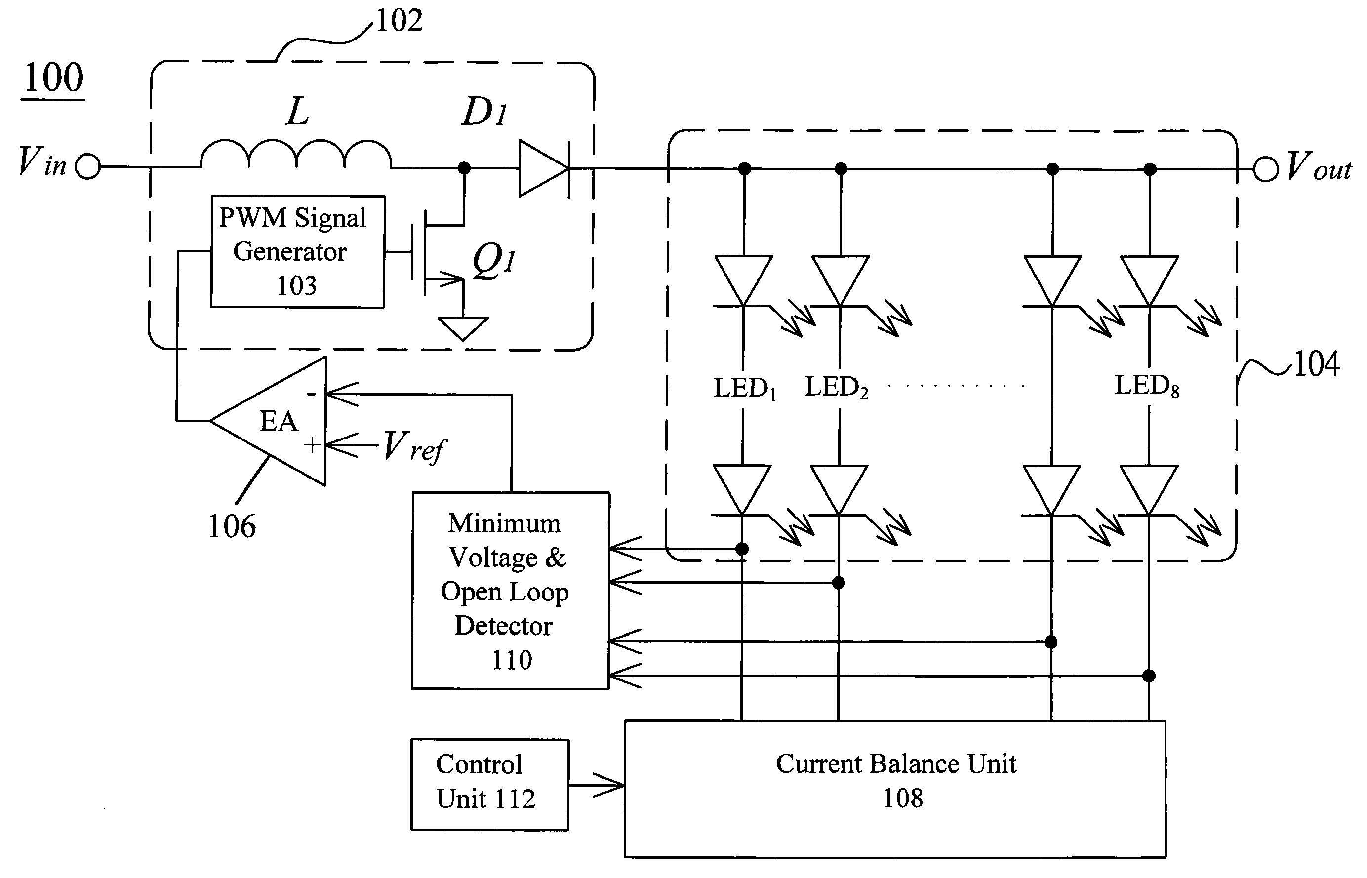
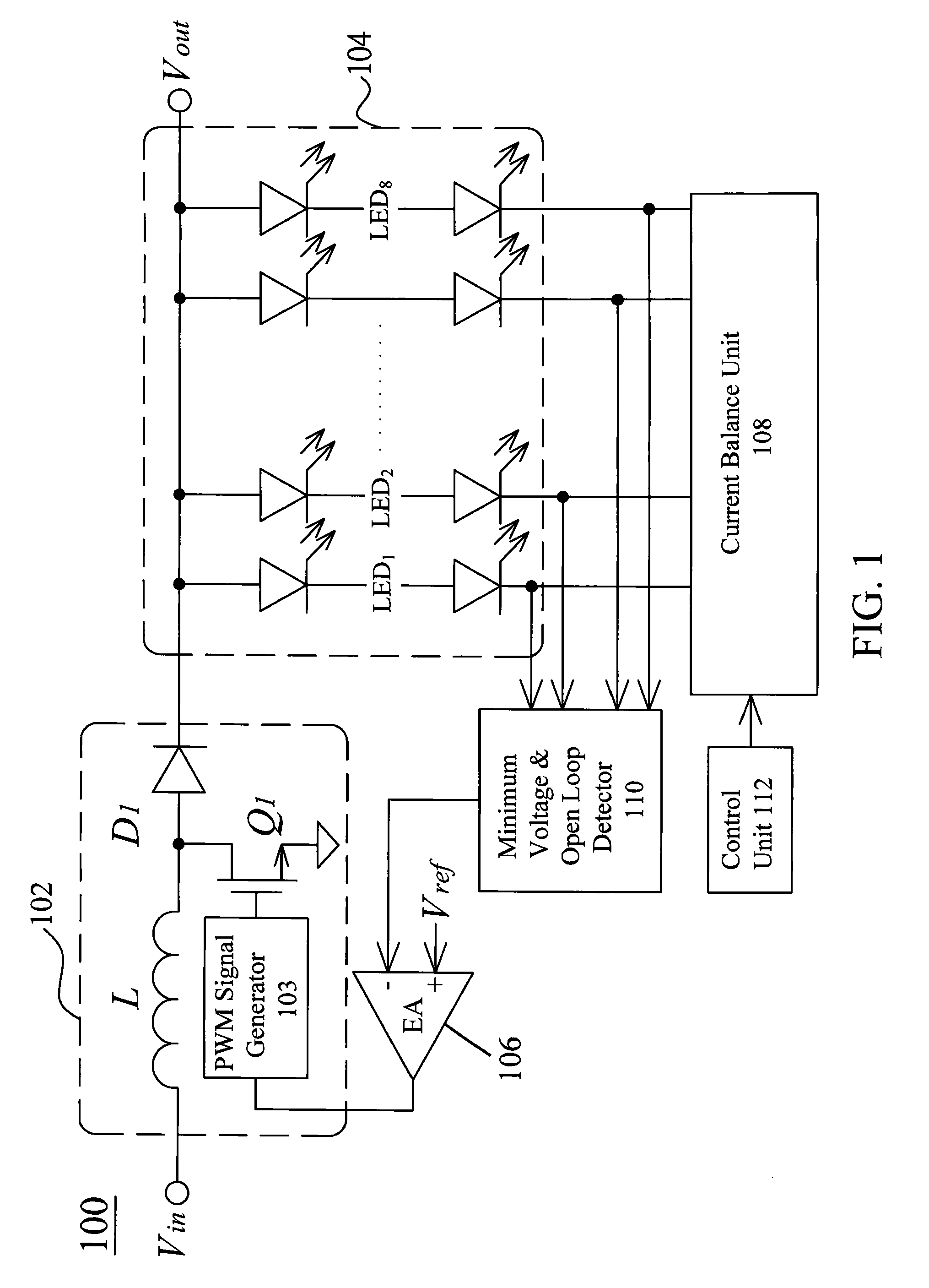
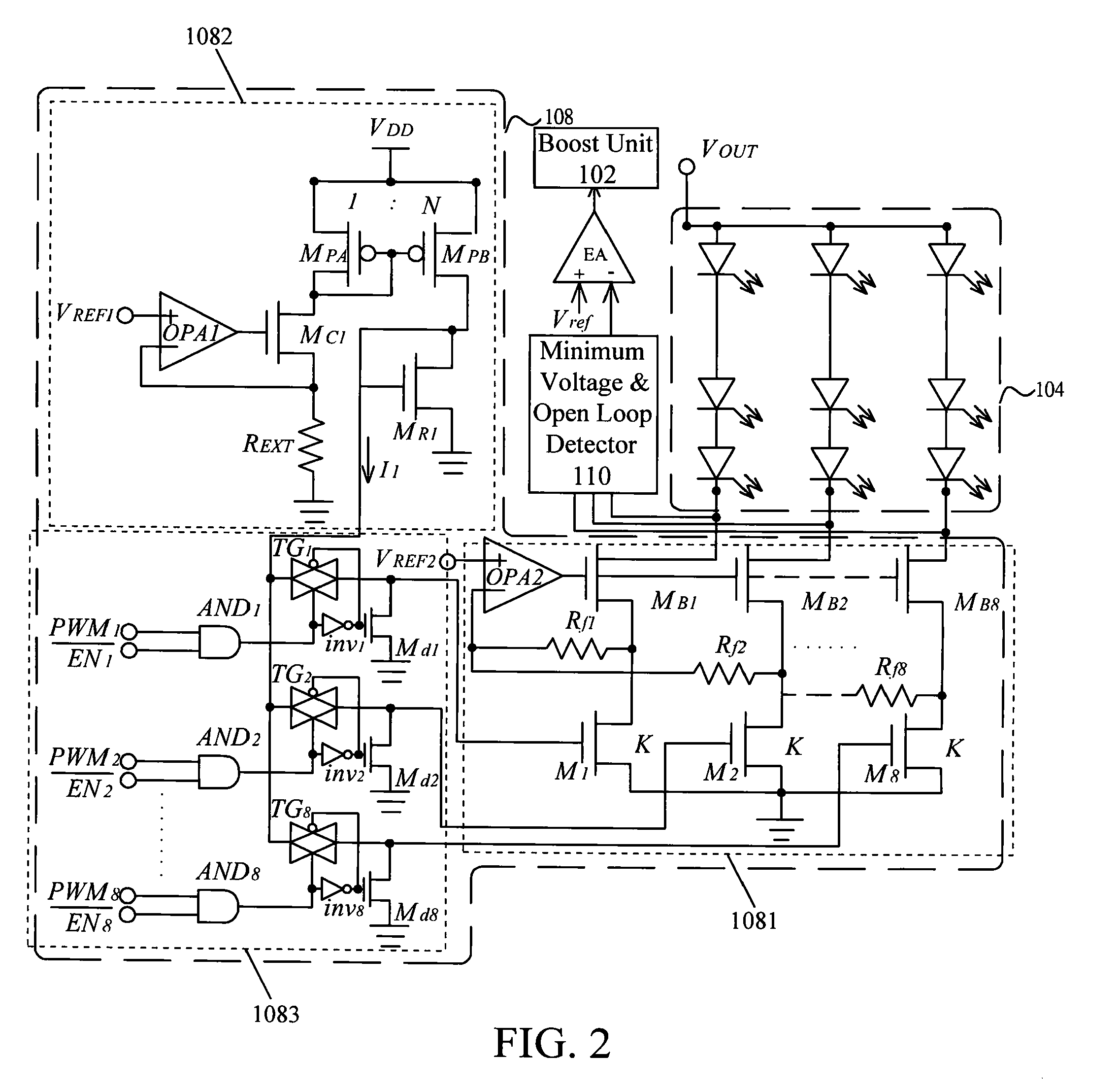
The present invention is a current balance circuit that improves the reliability and efficiency of driving currents and luminance for backlighting. It can effectively decrease the factors that affect the current, such as the characteristics of boost converter and LED, by ignoring error signals caused by damaged LED serial paths. The circuit can detect the minimum operating voltage for LEDs connected in series and adjust the output voltage to provide minimum operating voltages to a plurality of light units, reducing extra power consumptions and raising the efficiency of backlight modules. It is less complex and reduces power consumption, area of the chip, and number of pins on chip for the LED driving circuit, lowering the cost. The driving current for the LED can be defined by the user, without any need to re-modify the chip's internal circuit.

Problems solved by technology

The technical problem addressed in this patent is the inaccuracy of conventional LED driving methods due to differences in process or material, as well as errors caused by internal resistance on LEDs and the driving current. The patent proposes a solution using operational amplifiers to improve current matching between channels, but the prior art method requires a more complex circuit and higher cost on production.

Method used


Image

  • Current-balance circuit and backlight module having the same
  • Current-balance circuit and backlight module having the same
  • Current-balance circuit and backlight module having the same

Examples


Embodiment Construction

[0018]Some preferred embodiments of the present invention will now be described in greater detail. However, it should be recognized that the preferred embodiments of the present invention are provided for illustration rather than limiting the present invention. In addition, the present invention can be practiced in a wide range of other embodiments besides those explicitly described, and the scope of the present invention is not expressly limited except as specified in the accompanying claims.

[0019]References in the specification to “one embodiment” or “an embodiment” refers to a particular feature, structure, or characteristic described in connection with the preferred embodiments is included in at least one embodiment of the present invention. Therefore, the various appearances of “in one embodiment” or “in an embodiment” do not necessarily refer to the same embodiment. Moreover, the particular feature, structure or characteristic of the invention may be appropriately combined in ...


PUM


Abstract

The present invention relates to a current-balance circuit and a backlight module having the same. The current balance circuit includes a current balance unit, a control unit, and a detection unit. The current balance unit is connected to a plurality of light units to regulate the current of the plurality of light units, independent from the effects of input voltage. The detection unit is connected to the plurality of light units and the current balance unit to detect the minimum operating voltage for the plurality of light units. The control unit, connected to the current balance unit, controls the operation of the plurality of light units.

Description


Claims


Application Information

Patent Timeline
Owner CHUNGHWA PICTURE TUBES LTD
Why Eureka
Try Eureka