
Transformer

Inactive Publication Date: 2010-06-17
DELTA ELECTRONICS INC
View PDF6 Cites 1 Cited by
  • Summary
  • Abstract
  • Description
  • Claims
  • Application Information

AI Technical Summary

Benefits of technology

[0011]The transformer of this invention regulates the magnitude of the input voltage by providing the additional feedback winding area on the winding frame to prevent the transformer from being burnt out when the input voltage exceeds a rated input voltage. Meanwhile, because the core assembly of the transformer of this invention is made of a nonconductive material, the fixed safety distance is further minimized, thereby resulting in a miniaturized transformer.

Problems solved by technology

If the input voltage exceeds the rated input voltage of the transformer 1, the transformer would be burnt out, thereby causing damage to the electronic product where the transformer 1 is installed.

Method used


Image

  • Transformer
  • Transformer
  • Transformer

Examples


Embodiment Construction

[0016]In the following description, this invention will be explained with reference to embodiments thereof. However, these embodiments are not intended to limit this invention to any specific environment, applications or implementations described in these embodiments. Therefore, description of these embodiments is only for purposes of illustration rather than to limit the present invention. It should be appreciated that in the following embodiments and the attached drawings, elements unrelated to this invention are omitted from depiction.

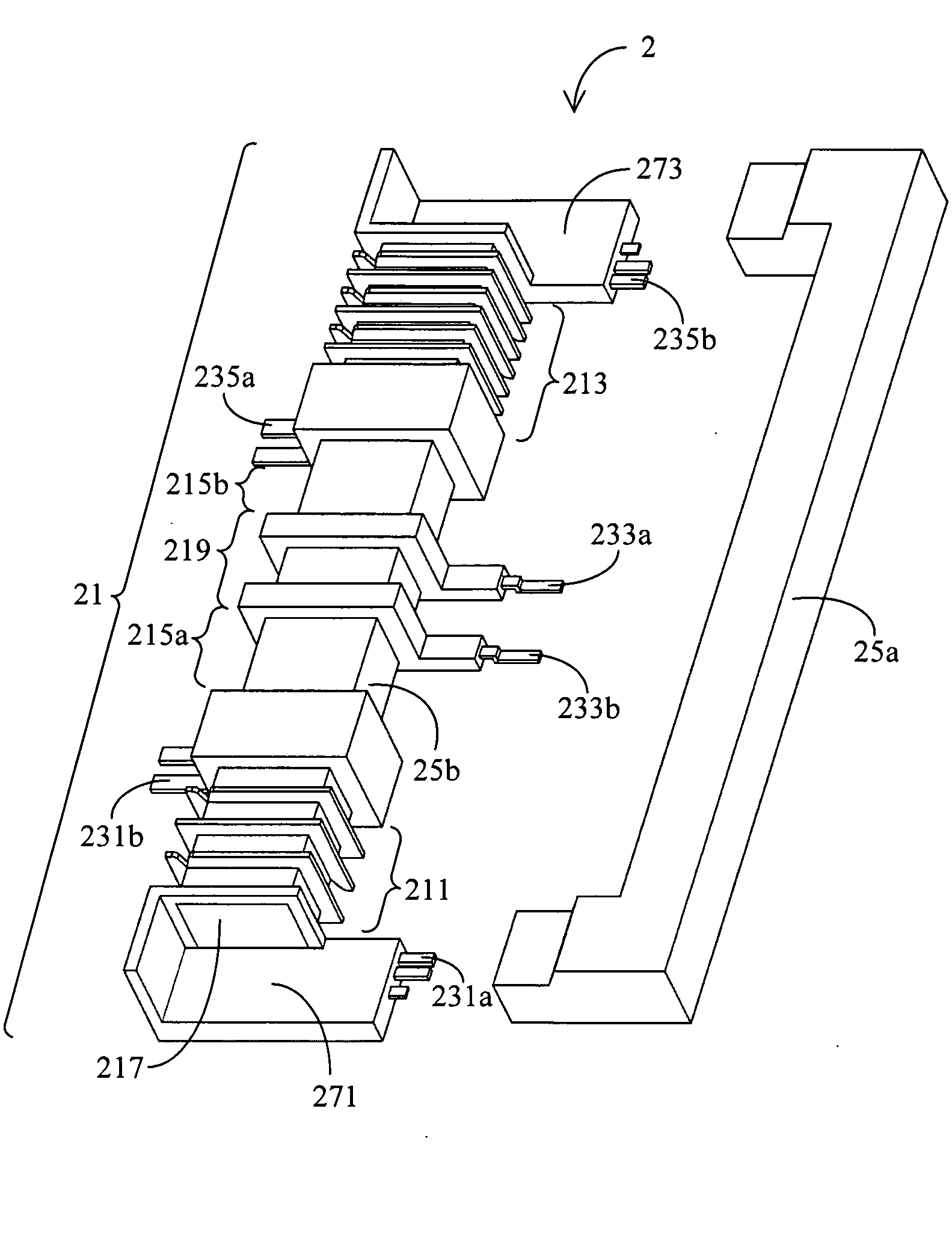
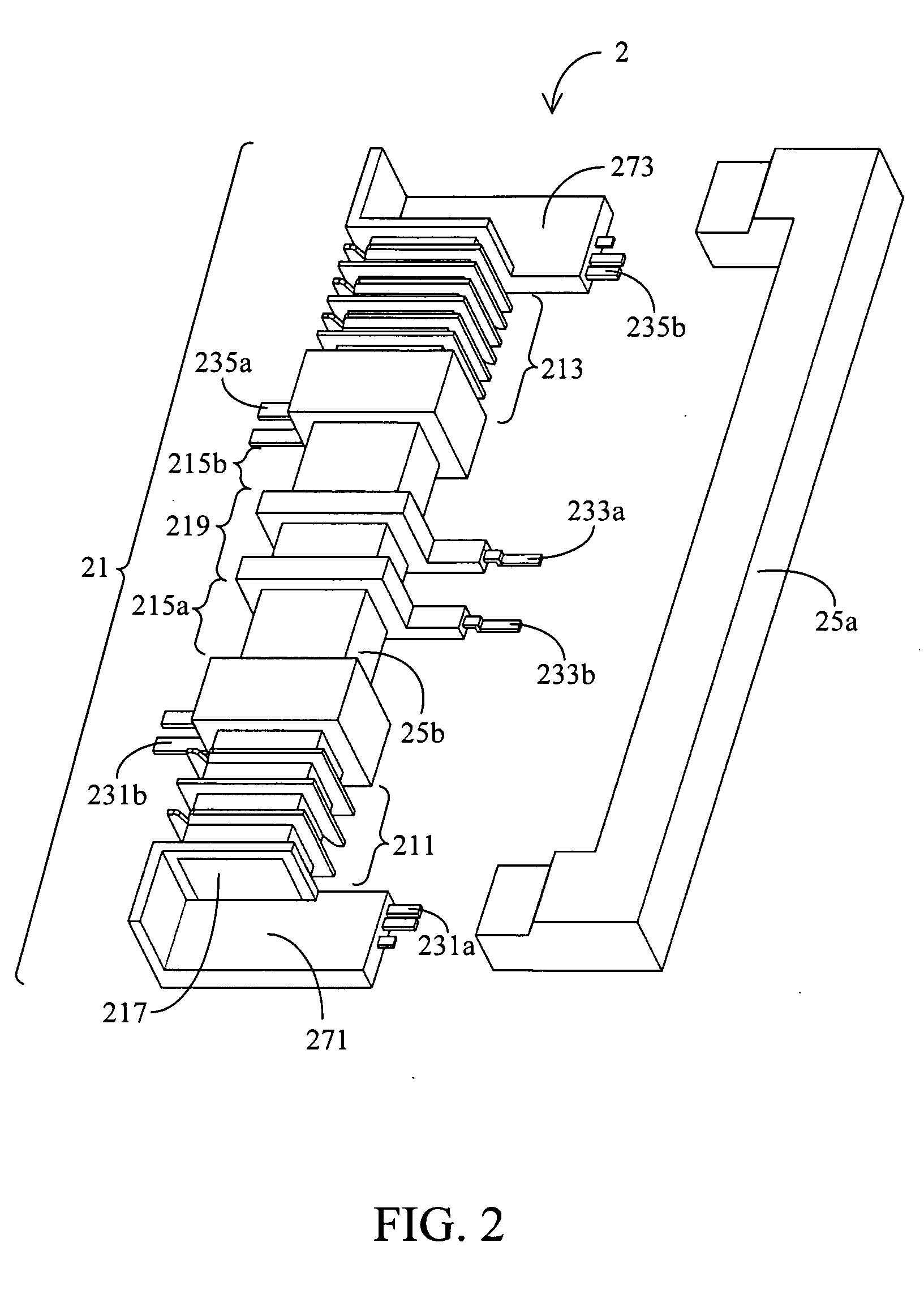
[0017]FIGS. 2 and 3 are schematic views of a transformer 2 according to a preferred embodiment of this invention. The transformer 2 comprises a winding frame 21 and a core assembly comprising a first core 25a and a second core 25b. The winding frame comprises at least one primary winding area 211, at least one secondary winding area 213, at least one feedback winding area 219 and at least two disposed areas 271, 273. The feedback winding area 219 is...


PUM


Abstract

A transformer which comprises a winding frame, at least one primary coil assembly, and at least one feedback coil assembly is provided. The winding frame has at least one primary winding area and at least one feedback winding area. The at least one primary coil assembly which is wound around the at least one primary winding area and electrically connected to a microcontroller is configured to receive an input voltage. The at least one feedback coil assembly which is wound around the at least one feedback winding area and electrically connected to the microcontroller is configured to output an induced voltage to the microcontroller. The microcontroller is configured to adjust the input voltage received by the at least one primary coil assembly according to the induced voltage.

Description

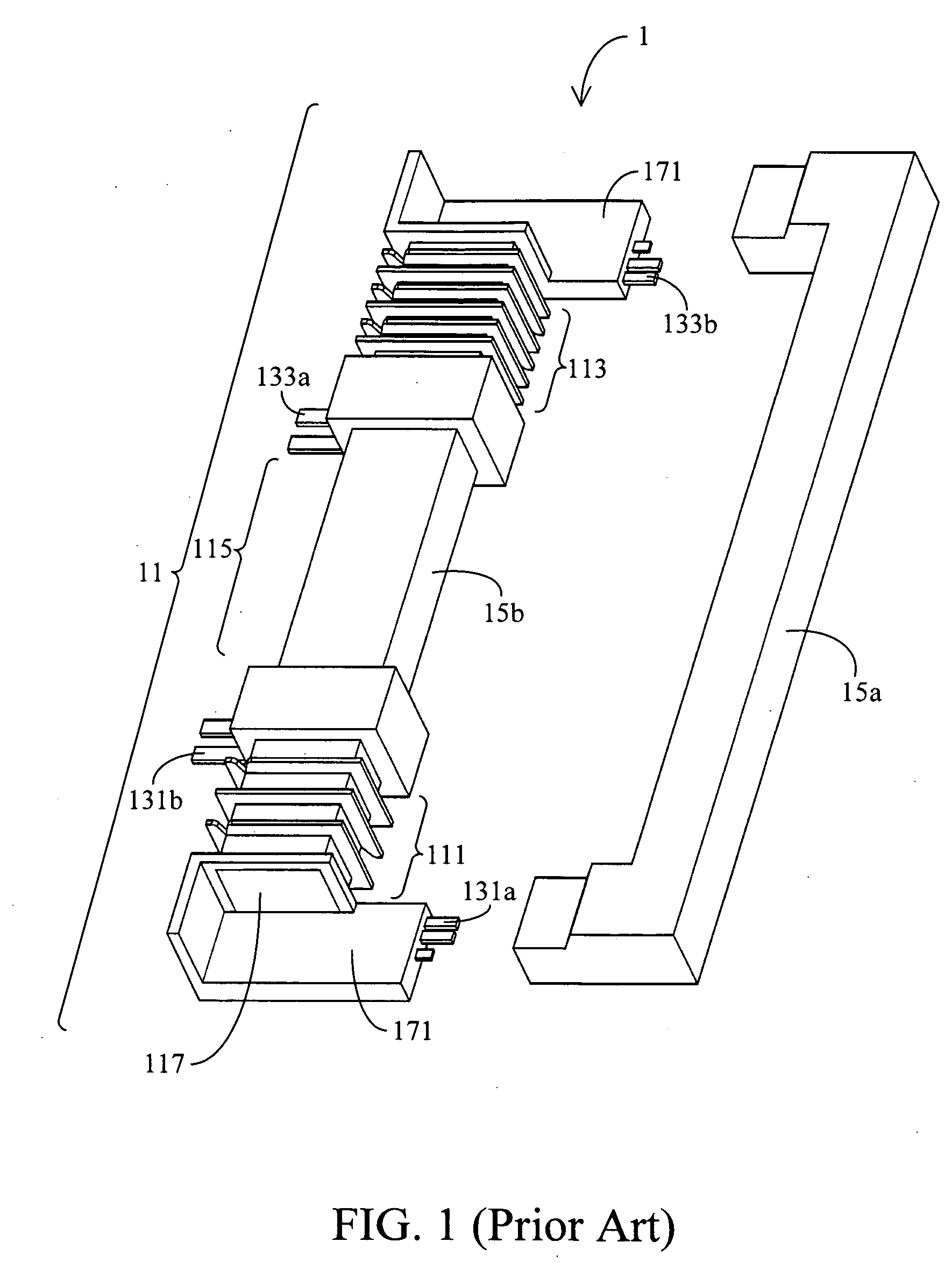
[0001]This application claims the benefit of priority based on Taiwan Patent Application No. 097222482, filed on Dec. 15, 2008, the contents of which is incorporated herein by reference in its entirety.CROSS-REFERENCES TO RELATED APPLICATIONS[0002]Not applicable.BACKGROUND OF THE INVENTION[0003]1. Field of the Invention[0004]The present invention relates to a transformer. More particularly, the present invention relates to a transformer for adjusting an input voltage via a microcontroller.[0005]2. Descriptions of the Related Art[0006]FIG. 1 depicts a conventional transformer 1, which comprises a winding frame 11 and a core assembly comprising a U-shaped core 15a and an I-shaped core 15b. The winding frame comprises a primary winding area 111, a secondary winding area 113, two disposed areas 171, a separating portion 115 and a jack 117. The two disposed areas 171 are disposed on two opposite ends of the winding frame 11. There is a separating portion 115 between the primary winding a...

Claims


Application Information

Patent Timeline
IPC IPC(8): H01F27/29
CPCH01F3/00H01F5/02H01F2005/022H01F27/38H01F27/402H01F27/266
Inventor KUNG, C. S.WU, H. X.FANG, CHANG-BING
Owner DELTA ELECTRONICS INC
Learn More