Printer with print head cleaning function

a printing head and function technology, applied in printing and other directions, can solve the problems of increasing cost, difficult and cost-intensive to precisely control the eccentric distance, and not always the same thickness of printing paper, and achieve the effect of cleaning the print head and fixed interference distan

Inactive Publication Date: 2009-03-24
QISDA CORP
View PDF5 Cites 2 Cited by
  • Summary
  • Abstract
  • Description
  • Claims
  • Application Information

AI Technical Summary

Benefits of technology

[0008]It is therefore an object of the invention to provide a printer which is dispensed with any electronic adjustment and capable of maintaining a fixed interference distance between the cleaner the cleaner and the print head for enabling the cleaner to clean the print head.
[0009]The invention achieves the above-identified object by providing a printer. The printer includes a housing, a round shaft, a carrier and a clean housing. The round shaft is disposed in the housing. The carrier is reciprocally disposed on the round shaft. The carrier is used for carrying one cartridge of the printer. The clean housing is equipped with a cleaner, which is used for cleaning one print head of the cartridge. When the carrier moves upward or downward, the carrier mechanically drives the clean housing to move upward or downward to maintain a fixed interference distance between the cleaner and the print head for enabling the cleaner to clean the print head and maintain the printing quality.

Problems solved by technology

However, the thickness of the printing paper is not always the same.
However, it is difficult and costive to control the eccentric distance precisely.
Such practice is an electronic control, and would further increase the cost.

Method used


Image

  • Printer with print head cleaning function
  • Printer with print head cleaning function
  • Printer with print head cleaning function

Examples


first embodiment

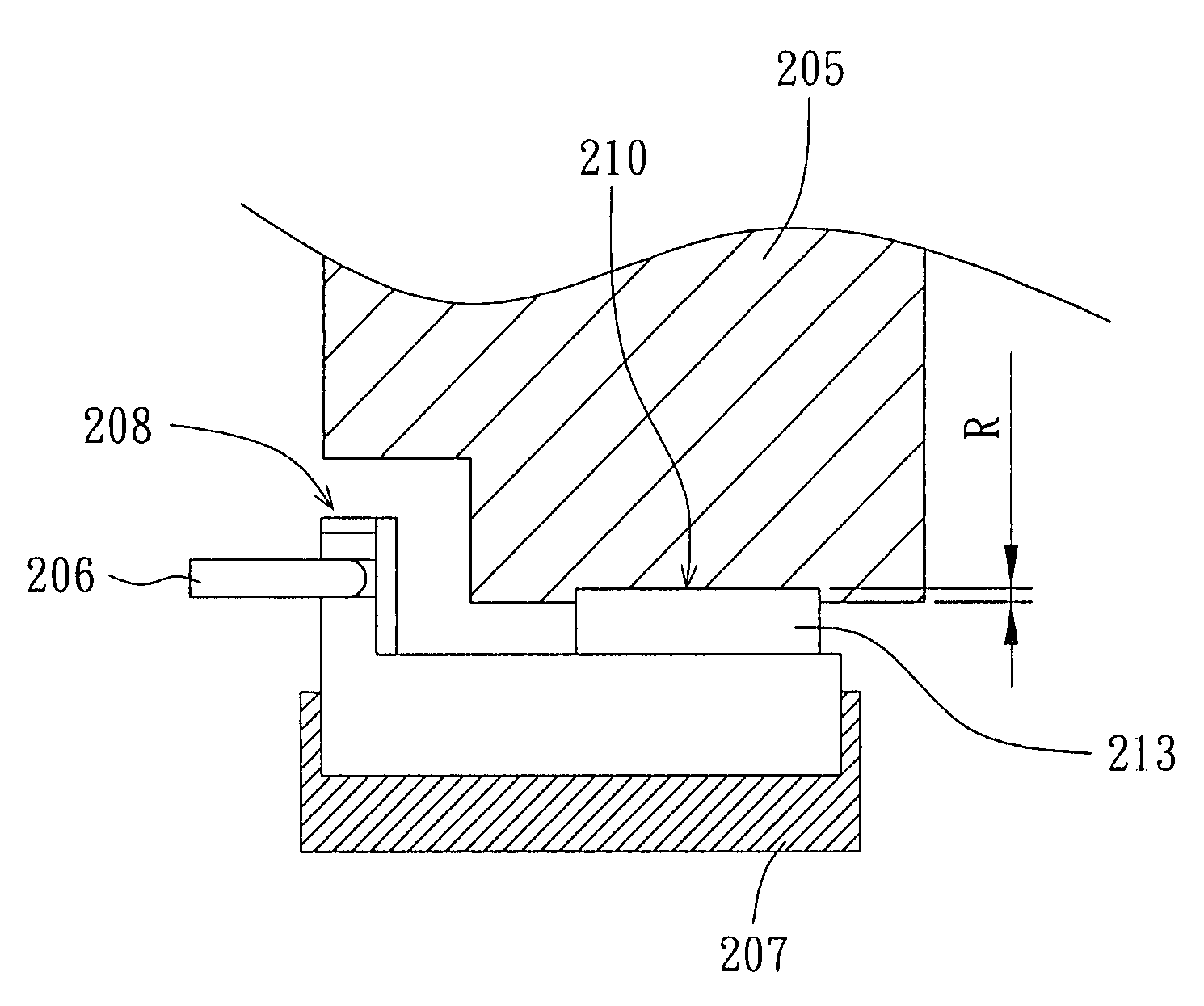
[0022]Referring to FIG. 2A, an exploded diagram of a printer is shown. The printer 200 includes a housing 201, a round shaft 203, a carrier 205 and a clean housing 207. The round shaft 203 is disposed in the housing 201, and is extended along an X direction. The carrier 205 has a pipe 211 disposed thereon (as shown in FIG. 2D). The pipe 211 is disposed on the round shaft 203 to drive the carrier 205 to reciprocate along the round shaft 203, so that the cartridge of the printer 200 such as cartridges 209a and 209b also reciprocate with the carrier 205. When the carrier 205 carries the cartridge to the position shown in FIG. 2A along the X direction, the carrier 205 drives the clean housing 207 for enabling the cleaner disposed on the clean housing 207 to clean the print head disposed on the cartridge. In order to match with various thicknesses of the printing paper, the height of the carrier 205 has to be adjusted accordingly. Therefore, the height of the clean housing 207 also has t...

second embodiment

[0027]Unlike the sliding contact between the protruding portion and the slide groove in the first embodiment, the contact between the protruding portion and the slide groove can be rolling contact in the second embodiment. The present embodiment involves two cases.

[0028]Referring to FIG. 3A to FIG. 3C, diagrams illustrating a protruding portion with a roller being engaged with a slide groove are shown. In the case of rolling contact, the first case is that a roller 320 is disposed at the terminal end of the protruding portion 306 for the protruding portion 306 and the slide groove 308 to have a smoother contact and produce a better effect in driving the carrier 305.

[0029]Referring to FIG. 4A to FIG. 4C, diagrams illustrating a slide groove with a roller are shown. The second case also occurs to the rolling contact except that in FIGS. 4A to 4C, the roller 420 is disposed in the slide groove 408, not on the protruding portion 406. Both cases are aimed to make the protruding portion e...


PUM


Abstract

A printer with print head cleaning function is provided. The printer includes a housing, a round shaft, a carrier and a clean housing. The round shaft is disposed in the housing. The carrier is reciprocally disposed on the round shaft. The carrier is used for carrying one cartridge of the printer. The clean housing is equipped with a cleaner, which is used for cleaning one print head of the cartridge. When the carrier moves upward or downward, the carrier mechanically drives the clean housing to move upward or downward to maintain a fixed interference distance between the cleaner and the print head for enabling the cleaner to clean the print head and maintain the printing quality.

Description

[0001]This application claims the benefit of Taiwan application Serial No. 94127222, filed on Aug. 10, 2005, the subject matter of which is incorporated herein by reference.BACKGROUND OF THE INVENTION[0002]1. Field of the Invention[0003]The invention relates in general to a printer, and more particularly to a printer with print head cleaning function.[0004]2. Description of the Related Art[0005]Referring to both FIG. 1A and FIG. 1B. FIG. 1A illustrates a side view of a cartridge and a document feeder of a printer, while FIG. 1B illustrates a partly enlarged diagram of FIG. 1A. The printer 100 includes a housing 101, a shaft 103, a carrier 105 and a document feeder. The carrier 105 is disposed on the shaft 103. The carrier 105 reciprocates along the shaft 103. The document feeder includes a roller 102a and a roller 102b. When the printing paper 140 is sent to the position shown in the diagram through the document feeder, the roller 102a and the roller 102b, the print head 110 of the ...

Claims


Application Information

Patent Timeline
Patent Type & Authority Patents(United States)
IPC IPC(8): B41J2/165
CPCB41J2/16517
Inventor ZHAO, MING-JIE
Owner QISDA CORP
Why Eureka
Try Eureka