Shielding of high voltage cables

a high-voltage cable and shielding technology, applied in the direction of power cables with screens/conductive layers, transmission, electrical equipment, etc., to achieve the effect of convenient installation and maintenan

Active Publication Date: 2014-11-25
PRYSMIAN SPA
View PDF16 Cites 2 Cited by
  • Summary
  • Abstract
  • Description
  • Claims
  • Application Information

AI Technical Summary

Benefits of technology

[0029]In the present description and attached claims, by “spaced portion” it is meant a cable portion cable length in which the distance between two cables is increased with respect to the close arrangement of a cable in a trench, thereby causing the magnetic field to increase.
[0048]Preferably the EMF shielding system further comprises two terminal boards electrically connecting the extremities of corresponding end portions of the first passive cables and the second passive cables together. This allows for an easy electrical connection of the passive cables, and further allows the inter-axis distance(s) of the passive cables to be fixed as desired.
[0050]By providing for an intermediate portion than need not receive any passive cable, its length may be easily changed to change the minimum spacing between the innermost pair of passive cables, i.e. between the two branches of the conductor.
[0053]The angle(s) may then be selected so that the first and second portions of the terminal boards are substantially perpendicular to the passive cables, that may therefore be more easily connected thereto.
[0061]In this way, the electrical coupling of the passive cables with the terminal boards is enhanced.
[0070]This allows for an easier installation and maintenance of the electric power distribution system, in that the EMF shielding system may be installed at a later time than any joints of the AC cables, and may be sized as a function of the EMF of the unshielded cable system.

Problems solved by technology

The Applicant faced the technical problem of lowering the magnetic field emitted by AC cables in locations where they are spaced from each other for a portion of their length.

Method used


Image

  • Shielding of high voltage cables
  • Shielding of high voltage cables
  • Shielding of high voltage cables

Examples


second embodiment

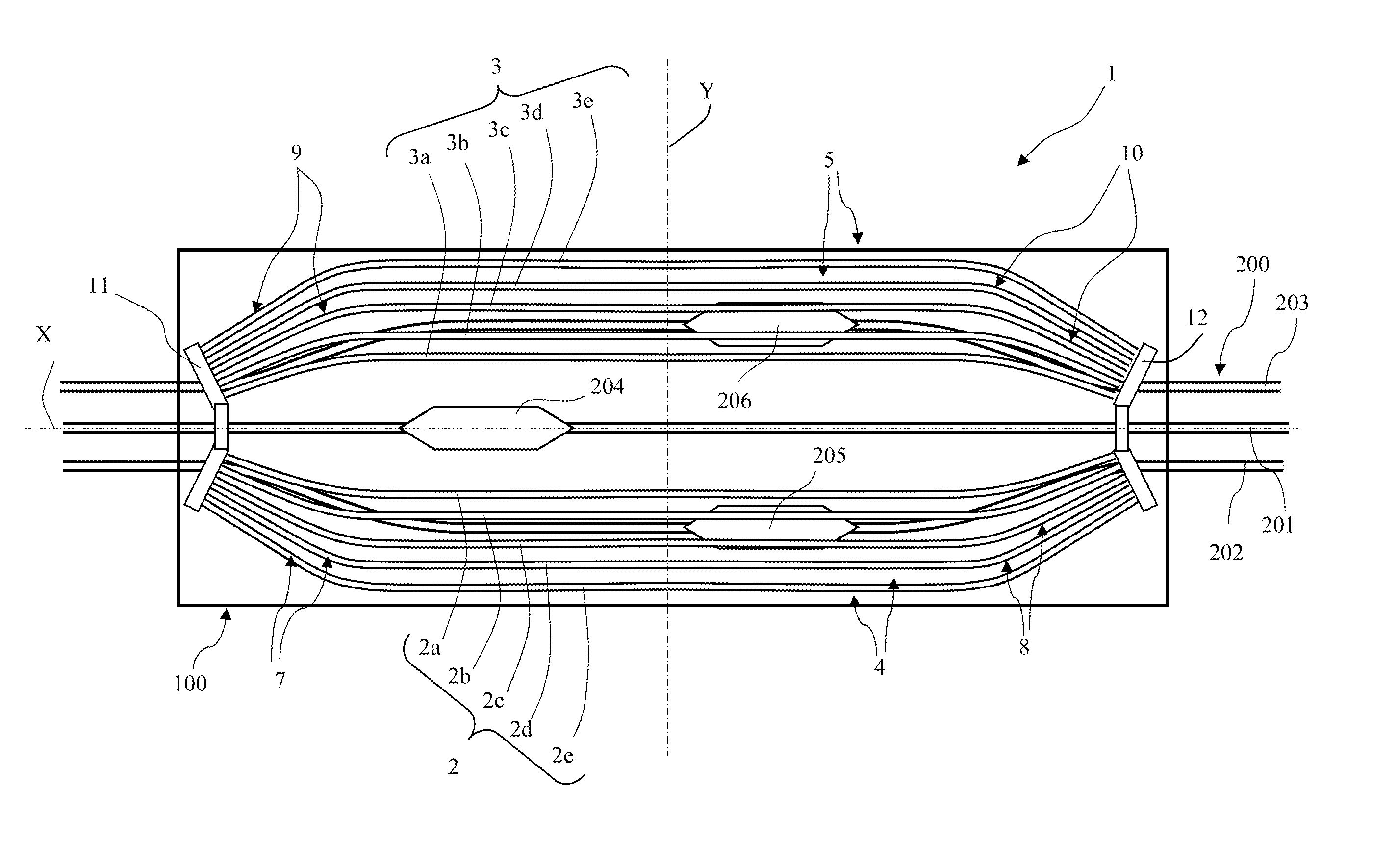
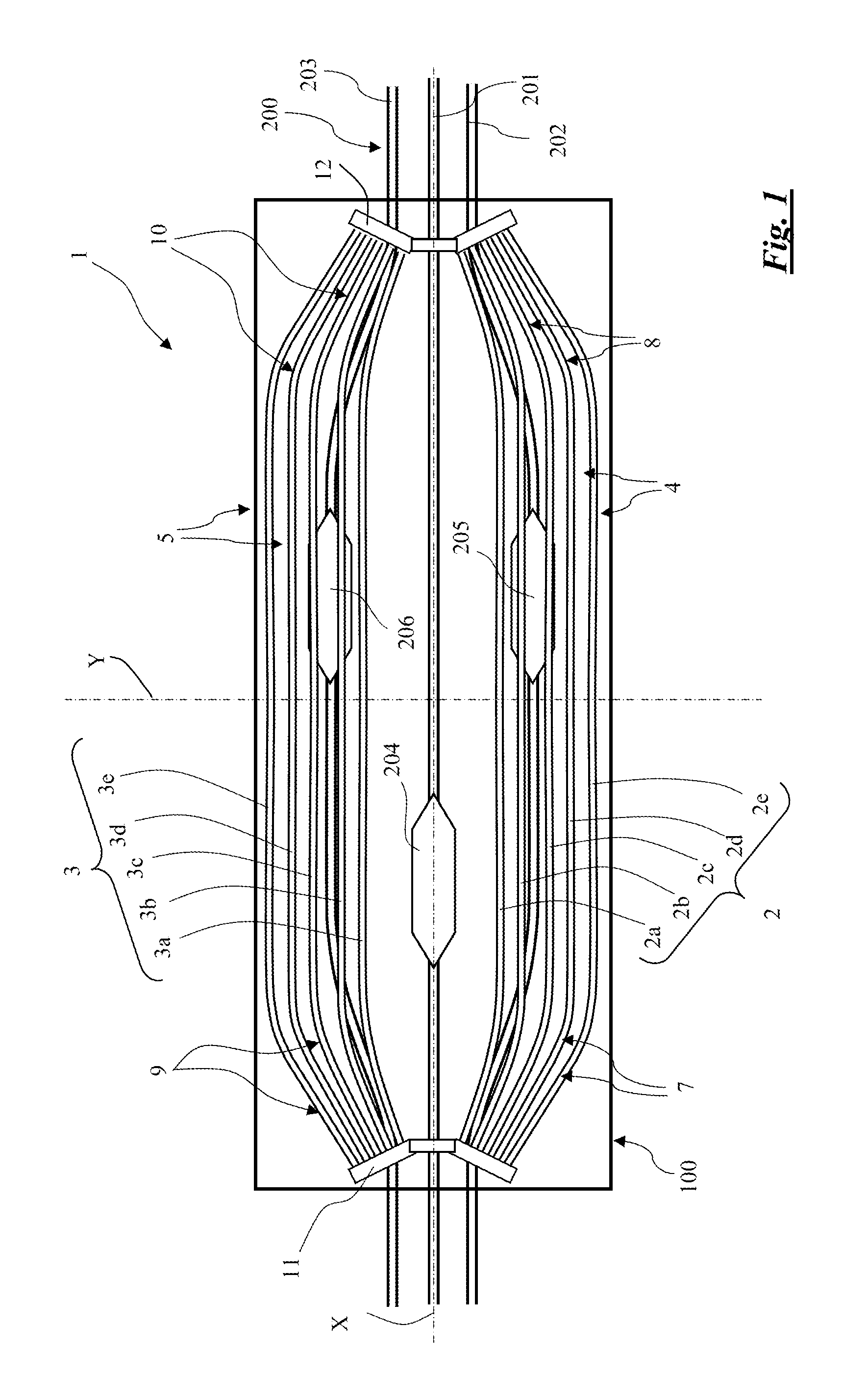
[0177]a passive cable EMF shielding 51 and a magnetically shielded cable arrangement according to the invention is schematically shown in FIG. 11, at joint bay 100.

first embodiment

[0178]Shielding 51 differs from shielding 1 of the first embodiment only in that it is shorter along the longitudinal axis X of the joint bay 100, and the variants disclosed above in respect of shielding 1 apply to this embodiment also.

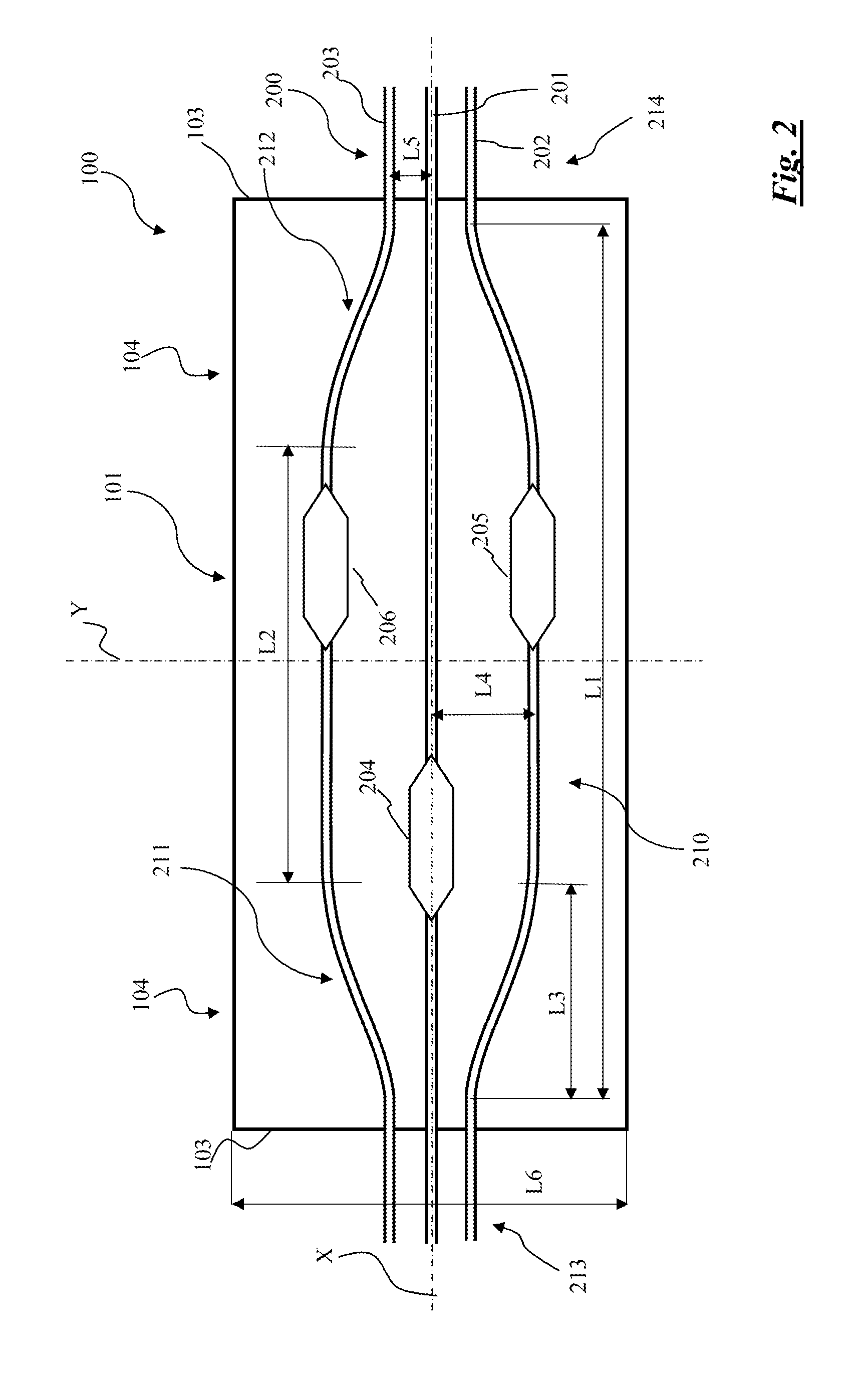
[0179]More in particular, in shielding 51 the median portions 54, 55 of passive cables 52, 53 only extend along the entire length of the central or widely spaced portion 210 of AC cable system 200, but do not extend over the transition portions 211, 212 of AC cable system 200, so that C is equal to L2. This is however not strictly necessary, as will be clear hereinafter.

[0180]The end portions 57-60 of passive cables 52, 53 extend along part of the transition portions 211, 212 of AC cable system 200, so that D is shorter than L3 when, as in FIG. 11, the preferred formula below holds true

C=L2  (5).

[0181]Preferably, the length D of the converging end portions 57-60 of shielding 51 is given by the formula

D=L3*2 / 3  (6)

[0182]In the shielding 51, the median ...

third embodiment

[0186]a passive cable EMF shielding 71 and a magnetically shielded cable arrangement according to the invention is schematically shown in FIG. 12, at joint bay 100.

[0187]Shielding 71 differs from shielding 51 of the second embodiment only in that it comprises additional cables 72-75, arranged in pairs at each terminal board 11, 12, longitudinally outwardly. More specifically, additional cable 72 is connected at a first end to first portion 13 of first terminal board 11, and additional cable 73 is connected at a first end to second portion 15 of first terminal board 11, their opposite ends being connected to each other. Similarly, additional cable 74 is connected at a first end to first portion 14 of second terminal board 12, and additional cable 75 is connected at a first end to second portion 16 of second terminal board 12, their opposite ends being connected to each other.

[0188]Additional cables 72-75 converge towards longitudinal axis X.

[0189]Additional cables 72-75 preferably ex...


PUM

PropertyMeasurementUnit
angleaaaaaaaaaa
angleaaaaaaaaaa
currentaaaaaaaaaa

Abstract

A magnetically shielded cable arrangement, comprising at least two AC cables (201-203) comprising a spaced portion extending between two close portions of parallel cables, such spaced portion sequentially including a diverging portion, a widely spaced portion and a converging portion, and an EMF shielding system (1) laid over said at least two AC cables (201-203), said EMF shielding system (1) comprising a conductor (2, 3, 11, 12) having two branches (2, 3) forming a median portion (4, 5) and end portions (7-10), the median portion width being equal to or larger than the AC cables distance in the widely spaced portion and the width at the extremities of the end portions (7-10) being larger than the AC cables distance in the close portions and smaller than the AC cables distance in the widely spaced portion, said conductor (2, 3, 11, 12) comprising an inner electrical path (2a, 3a) and an outer electrical path (2e, 3e) connected together (11, 12) at relevant longitudinal ends.

Description

CROSS-REFERENCE TO RELATED APPLICATION(S)[0001]This application is a national stage entry from International Application No. PCT / EP2010 / 002517, filed on Apr. 23, 2010, in the Receiving Office of the European Patent Office, the entire contents of which are incorporated herein by reference.BACKGROUND OF THE INVENTION[0002]The present invention relates to the shielding of high voltage (HV) cable systems.[0003]The present invention relates more in particular to the Electro Magnetic Field (EMF) shielding of underground AC three-phase HV cables in joint bays, manholes and joint chambers, as well as in other places where, for any reason, the cables are spaced from each other for a length, such as to go round an obstacle in the path of the cables.[0004]For the sake of brevity, joint bays will be mostly referred to hereinbelow.[0005]In the present description and claims the terms:[0006]“High Voltage” or HV is used to indicate voltages higher than 35 kV, i.e. it is broadly used to include “Ex...

Claims


Application Information

Patent Timeline
Patent Type & Authority Patents(United States)
IPC IPC(8): H02G9/10H02G9/02H01B9/02H01B11/02
CPCH02G9/02H02G9/10H01B9/02
Inventor MAIOLI, PAOLO
Owner PRYSMIAN SPA
Why Eureka
Try Eureka