
Ink jet print head and printing method and apparatus using the same

a printing head and jet printer technology, applied in printing and other directions, can solve the problems of reducing the print duty per unit time, high print duty, and increasing so as to reduce the impact of self air flow, increase the amount of end deviation, and increase the effect of print duty

Inactive Publication Date: 2010-06-17
CANON KK
View PDF8 Cites 8 Cited by
  • Summary
  • Abstract
  • Description
  • Claims
  • Application Information

AI Technical Summary

Benefits of technology

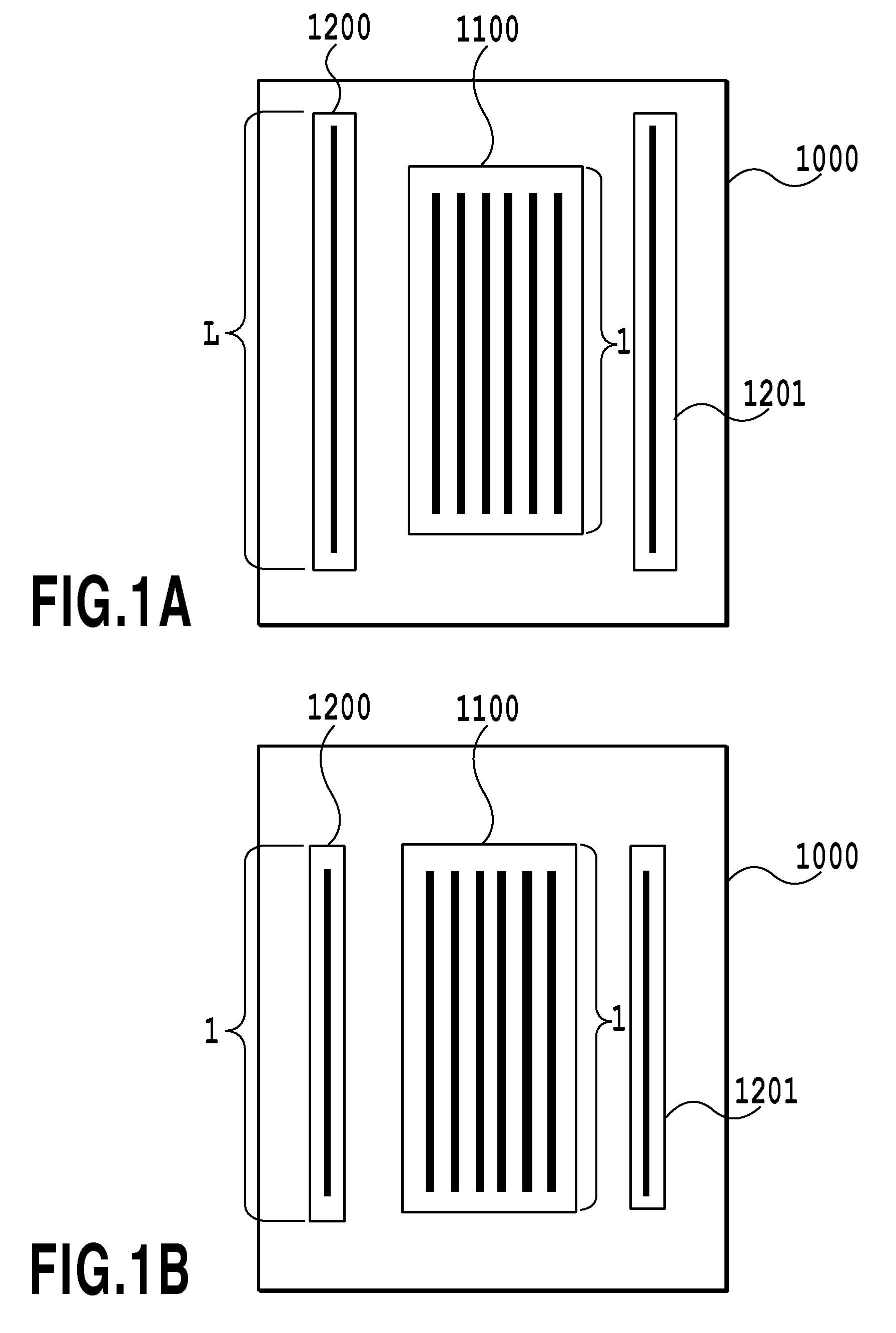
The present invention relates to an ink jet print head that reduces the impact of self air flow to improve image quality. The print head includes a black ink ejection chip and a color ink ejection chip, with the black ink ejection ports having a larger ejection amount than the color ink ejection ports. The black ink ejection chips are arranged on the opposite sides of the color ink ejection chip, which increases the distance between the ejection port rows and prevents self air flows from affecting each other. This results in a reduction of end deviation and the elimination of white stripes in printed images. The invention also includes a method for reducing self air flow by increasing the ejection amount of ink droplets and increasing the distance between the ejection port rows.

Problems solved by technology

(1) A high print duty generally tends to increase the amount of end deviation.
That is, if the same amount of ink droplets are ejected, ejection of larger droplets at a lower density reduces the print duty per unit time compared to ejection of smaller droplets at a higher density.
This makes the printing unlikely to be affected by the self air flow.

Method used


Image

  • Ink jet print head and printing method and apparatus using the same
  • Ink jet print head and printing method and apparatus using the same
  • Ink jet print head and printing method and apparatus using the same

Examples


first embodiment

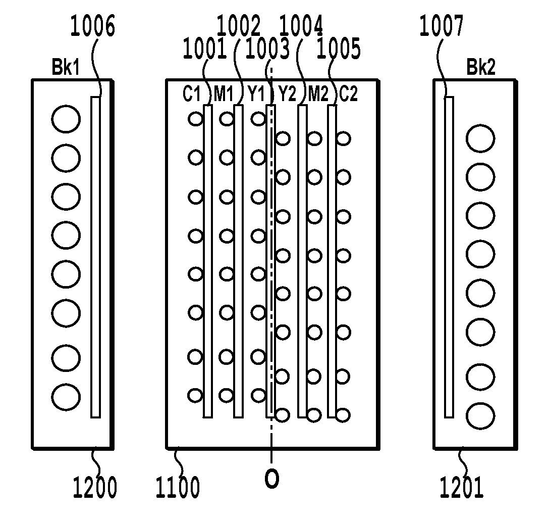
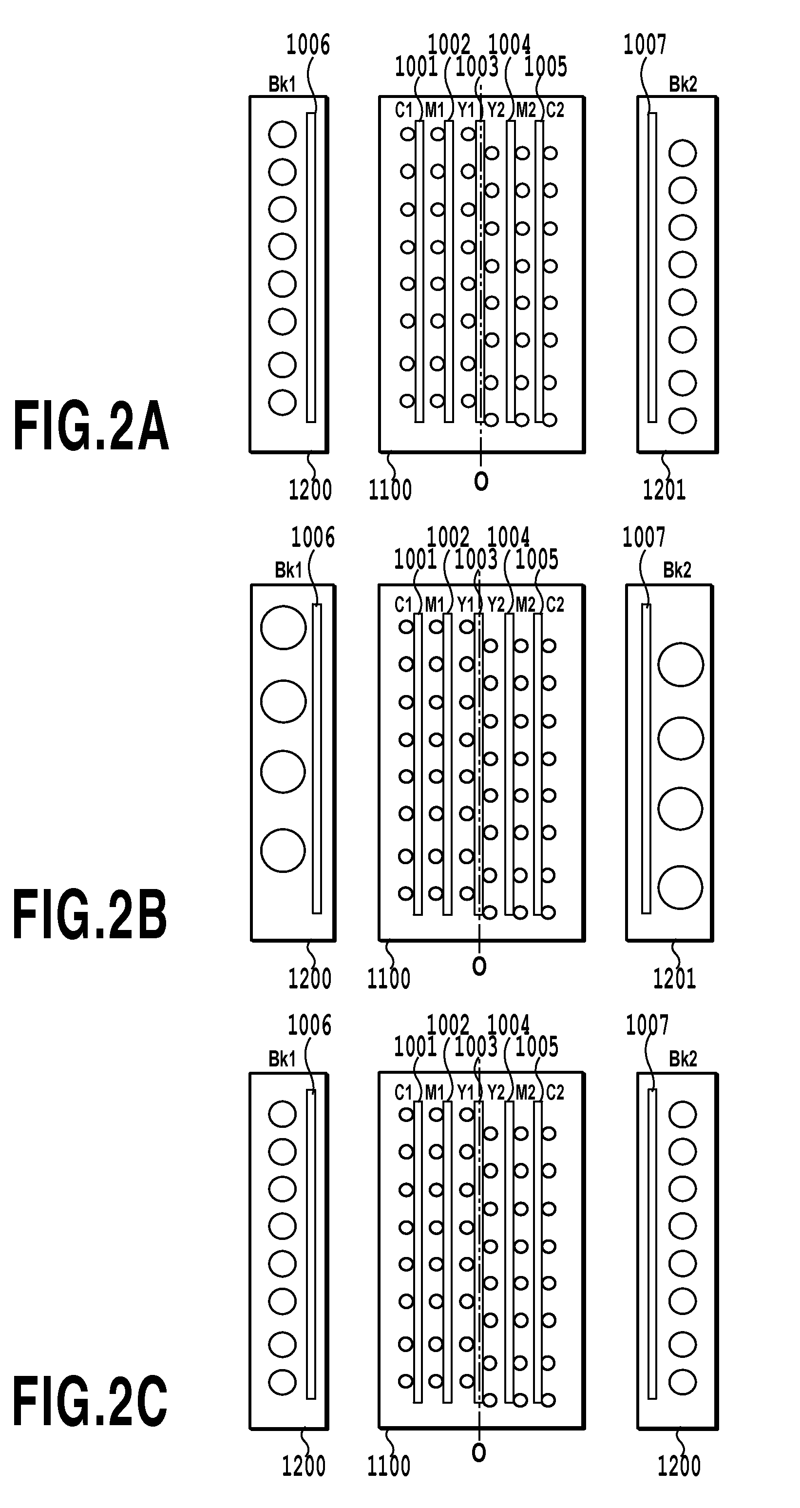
[0073]Thus, in the ink jet print head according to the present invention, the ejection ports are arranged as shown in FIG. 2A based on the results shown in FIG. 4. Furthermore, the amount of black ink ejected is set to 10 pl, and the amount of color ink ejected is set to 5 pl. In the present embodiment, the plurality of ejection ports making up the corresponding ejection port rows Bk1 and Bk2 in the first and second black ink ejection chips 1200 and 1201 are staggered with respect to one another (staggered arrangement). Also, the plurality of ejection ports making up the ejection port rows C1 and C2 in the color ink ejection chip 1100 through which cyan ink is ejected are staggered with respect to one another. Similarly, the plurality of ejection ports making up the ejection port rows M1 and M2 though which magenta ink is ejected are staggered with respect to one another. The plurality of ejection ports making up the ejection port rows Y1 and Y2 though which yellow ink is ejected ar...

second embodiment

[0075]FIG. 2B shows a second embodiment of the ink jet print head according to the present invention. The present embodiment is the same as the first embodiment except for the amount of black ink and the nozzle resolution of the black ink ejection ports. That is, in the present embodiment, the amount of black ink ejected is set to 20 pl, and the amount of color ink ejected is set to 5 pl as is the case with the first embodiment. Furthermore, the nozzle resolution of the black ink ejection ports is 600 dpi, and the nozzle resolution of the color ink ejection ports is 1,200 dpi as is the case with the first embodiment.

[0076]Also in the present embodiment, the amount of black ink ejected is set to be larger than that of color ink ejected. Furthermore, the first and second black ink ejection chips 1200 and 1201 are separately arranged on the respective sides of the color ink ejection chip 1100. Thus, the present embodiment exerts the same effects as those of the first embodiment.

third embodiment

[0077]FIG. 2C shows a third embodiment of the ink jet print head according to the present invention. The present embodiment is the same as the first embodiment except that the black ink ejection port rows Bk1 and Bk2 in each of the first and second black ink ejection chips 1200 and 1201 in the above-described first embodiment are not staggered with respect to each other. That is, in the present embodiment, as is the case with the first embodiment, the amount of black ink ejected is set to 10 pl, and the amount of color ink ejected is set to 5 pl. Furthermore, the nozzle resolution of the black ink ejection ports is 600 dpi, and the nozzle resolution of the color ink ejection ports is 1,200 dpi as is the case with the first embodiment. Printing performed by the ink jet print head according to the present embodiment is expected to be as effective as that performed by the ink jet print heads according to the first and second embodiments.


PUM


Abstract

The present invention relates to measures for preventing end deviation that may occur during high-duty printing such as one-pass printing, and in particular, to measures for preventing density unevenness (white stripes) in the case of ink with a low lightness such as black ink. According to the present invention, the amount of black ink ejected through the corresponding ejection ports is set to be larger than that of color ink ejected through the corresponding ejection ports. Two black ink ejection chips each having at least one black ink ejection port row are arranged on the respective sides of a color ink ejection chip.

Description

BACKGROUND OF THE INVENTION[0001]1. Field of the Invention[0002]The present invention relates to an ink jet print head having ejection ports through which ink is ejected, and a printing method and apparatus using the ink jet print head.[0003]2. Description of the Related Art[0004]For a printing apparatus forming images on printing media, particularly an ink jet printing apparatus, an important subject is to increase the speed of color printing on plain papers or the like and to improve the quality of images.[0005]For the ink jet printing apparatus, common techniques for increasing the print speed include, besides an increase in the length of an ink jet print head, an increase in the printing (or driving) frequency of the print head and the use of bidirectional printing. Compared to unidirectional printing, the bidirectional printing temporally disperses energy required to achieve the same throughput. The bidirectional printing is thus effective means in terms of costs of toal system...

Claims


Application Information

Patent Timeline
Patent Type & Authority Applications(United States)
IPC IPC(8): B41J2/21
CPCB41J2/2121B41J2/2103B41J2/2125
Inventor MIZUTANI, MICHINARI
Owner CANON KK
Learn More