Circuit Breaker With Bistable Display

a circuit breaker and display technology, applied in the field of circuit breakers, can solve the problems of power to be restored, complicated fault diagnosis, power interruption between load and load

Active Publication Date: 2010-06-17
SCHNEIDER ELECTRIC USA INC
View PDF8 Cites 36 Cited by
  • Summary
  • Abstract
  • Description
  • Claims
  • Application Information

AI Technical Summary

Benefits of technology

[0008]One disclosed example is a circuit breaker that includes a bi-stable display. A bi-stable display is a display that maintains an image without power. In this example, the bi-stable display maintains an indicator of a fault that caused the circuit breaker to trip regardless of whether power is maintained to the bi-stable display. In this manner, an electrician or homeowner may quickly tell the cause of the trip condition that caused the circuit breaker to interrupt power flow. This may aid in the diagnosis and solution of the problem that caused the power flow interruption.

Problems solved by technology

Various fault conditions trip the circuit breaker thereby interrupting power flow between the load and the power source.
Thus, fault diagnosis is complicated by the lack of information to assist a technician.
However, this requires power to be restored to power the LED fault display.
Such restored power is also supplied to the load side terminals creating a potential hazard since the cause of the fault may still be connected to the load side terminals.
Further, the fault condition must be stored in the memory of the circuit breaker thus taking up memory space.
The current circuit breaker designs therefore suffer from a problem of not having any indication of the fault that caused a tripped state when the power is turned off.

Method used


Image

  • Circuit Breaker With Bistable Display
  • Circuit Breaker With Bistable Display
  • Circuit Breaker With Bistable Display

Examples


Embodiment Construction

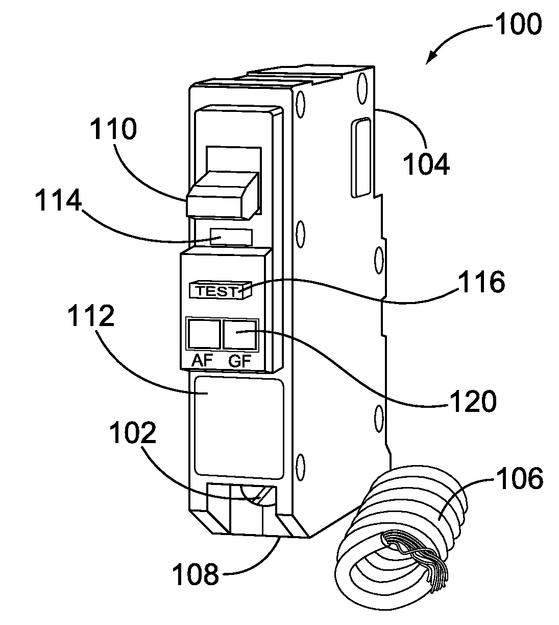
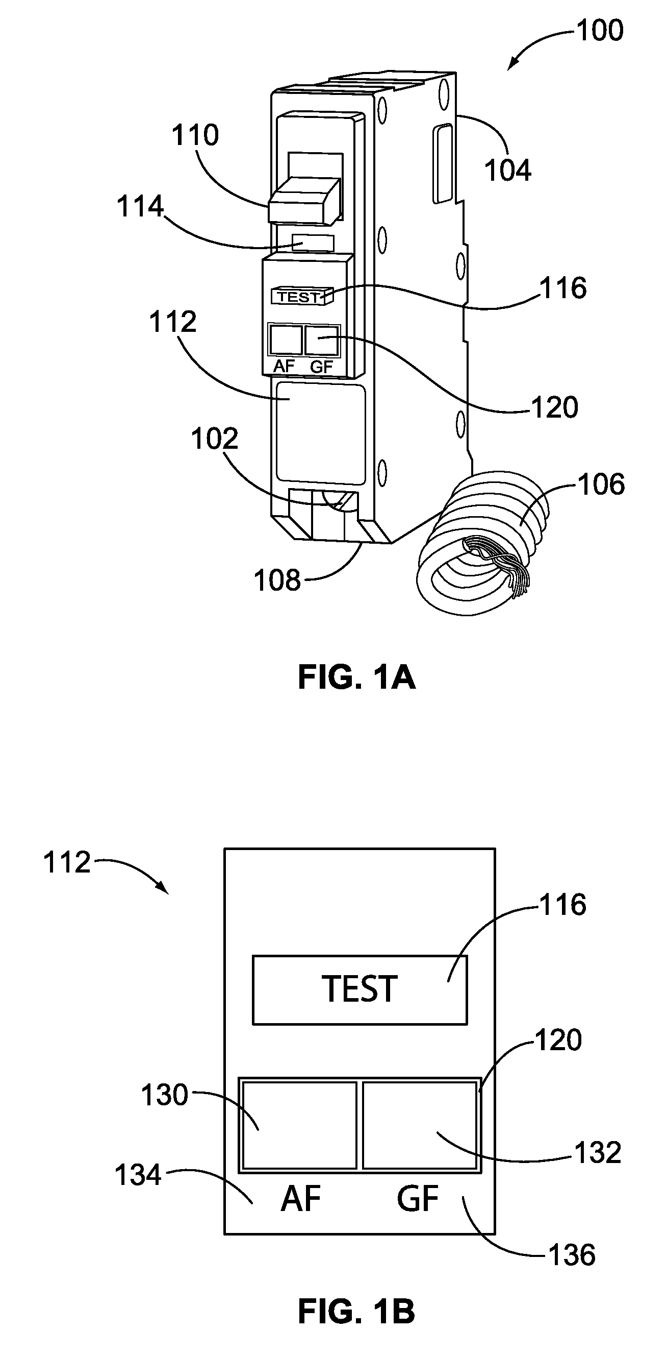
[0020]Turning now to FIG. 1A, a perspective view of a circuit breaker 100 is shown. The circuit breaker 100 includes a load side connector 102, a power line connector 104, a line neutral source wire 106 and a load neutral connector 108. A handle 110 connected to a trip mechanism (detailed below) is mounted on a front panel 112. The handle 110 may be placed in an on position (up position not shown in FIG. 1A) that causes the circuit breaker 100 to allow current flow between the power line connector 104 and the load side connector 102. The handle 110 may be placed in a tripped condition (down position shown in FIG. 1A) cutting off current flow between the power side connector 104 and the load side connector 102. A lens 114 is mounted below the handle 110 and shows an indication that the handle 110 is in a trip condition. A test button 116 is provided to test the internal electronics of the circuit breaker 100. A bi-stable display 120 is also mounted on the front panel 112. In this exa...


PUM


Abstract

A circuit breaker is disclosed that has a bi-stable display that maintains an indication of a fault condition after power is interrupted to the circuit breaker. The circuit breaker has a microcontroller that receives power derived from a line current that passes through the circuit breaker or the line voltage when the circuit breaker is in an on state. The bi-stable display is electrically coupled to and controlled by the microcontroller. A tripping mechanism trips the circuit breaker in response to detection of a fault condition. The tripping mechanism trips the circuit breaker in response to receiving a trip signal from the microcontroller. The microcontroller is programmed to modify the bi-stable display when sending the trip signal to the electronic switching device. The bi-stable display shows an indication of one of the several fault types that would have caused the circuit breaker to trip. The bi-stable display continues to display the fault-type indication after the circuit breaker has tripped and power is interrupted to the microcontroller.

Description

FIELD OF THE INVENTION[0001]Aspects disclosed herein relate generally to circuit breakers, and, more particularly, to a circuit breaker having a bistable display showing a fault condition after power is cutoff to the circuit breaker.BACKGROUND[0002]Circuit breakers provide automatic current interruption to a monitored circuit when undesired fault conditions occur. These fault conditions include, for example, arc faults, overloads, ground faults, and short-circuits. As is well-known, a circuit breaker is an automatically operated electromechanical device designed to protect branch wiring from damage caused by an overload or a short circuit. A typical circuit breaker has a load connector and a power connector with a break mechanism interposed between the load connector is (connected to a load device) and the power connector (connected to a power source such as a panel board). Various fault conditions trip the circuit breaker thereby interrupting power flow between the load and the pow...

Claims


Application Information

Patent Timeline
IPC IPC(8): H02H9/02G08B21/00
CPCH01H2071/042H01H71/04
Inventor LARSON, BRETTSCOTT, GARY
Owner SCHNEIDER ELECTRIC USA INC
Why Eureka
Try Eureka