Light source apparatus

a technology of light source and light source, which is applied in the direction of lighting and heating apparatus, point-like light source, lighting support devices, etc., can solve the problems of not meeting users' requirements for light intensity, reducing the light intensity of amber color leds, and reducing the luminance ratio, so as to achieve the effect of facilitating variation

Inactive Publication Date: 2010-06-17
YOUNG GREEN ENERGY
View PDF7 Cites 12 Cited by
  • Summary
  • Abstract
  • Description
  • Claims
  • Application Information

AI Technical Summary

Benefits of technology

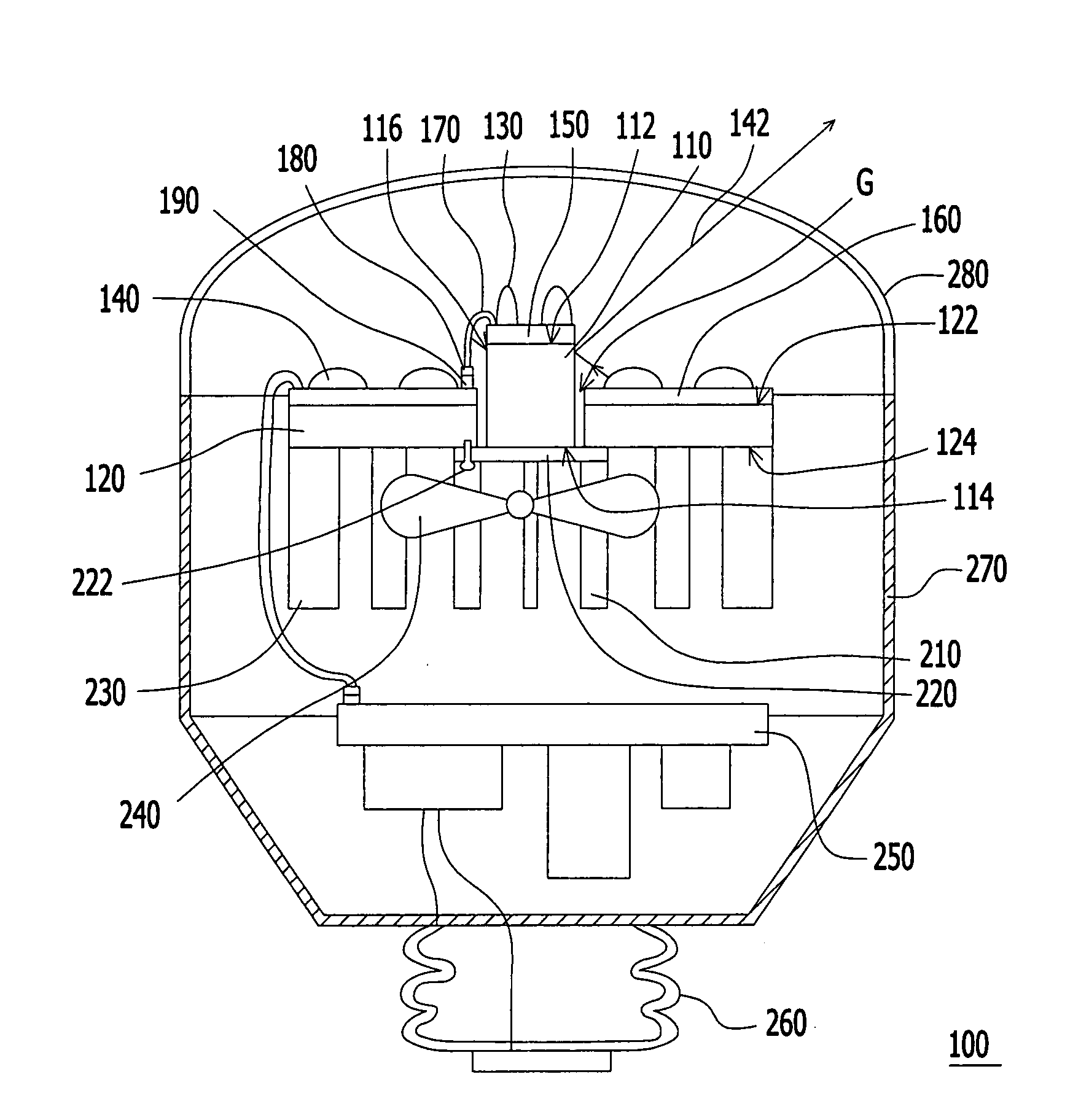
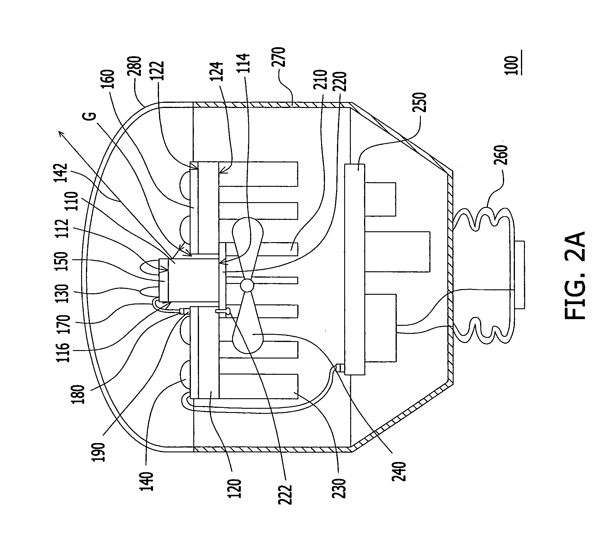
[0016]In the light source apparatus of the embodiment of the invention, since the thermal resistance of the first heat transfer element is smaller than the thermal resistance of the second heat transfer element, the first heat transfer element may rapidly conduct the heat away from the first light emitting element having the luminance being easier to vary with the change of temperature, so as to prevent the luminance of the first light emitting element from varying with the increase of working time.

Problems solved by technology

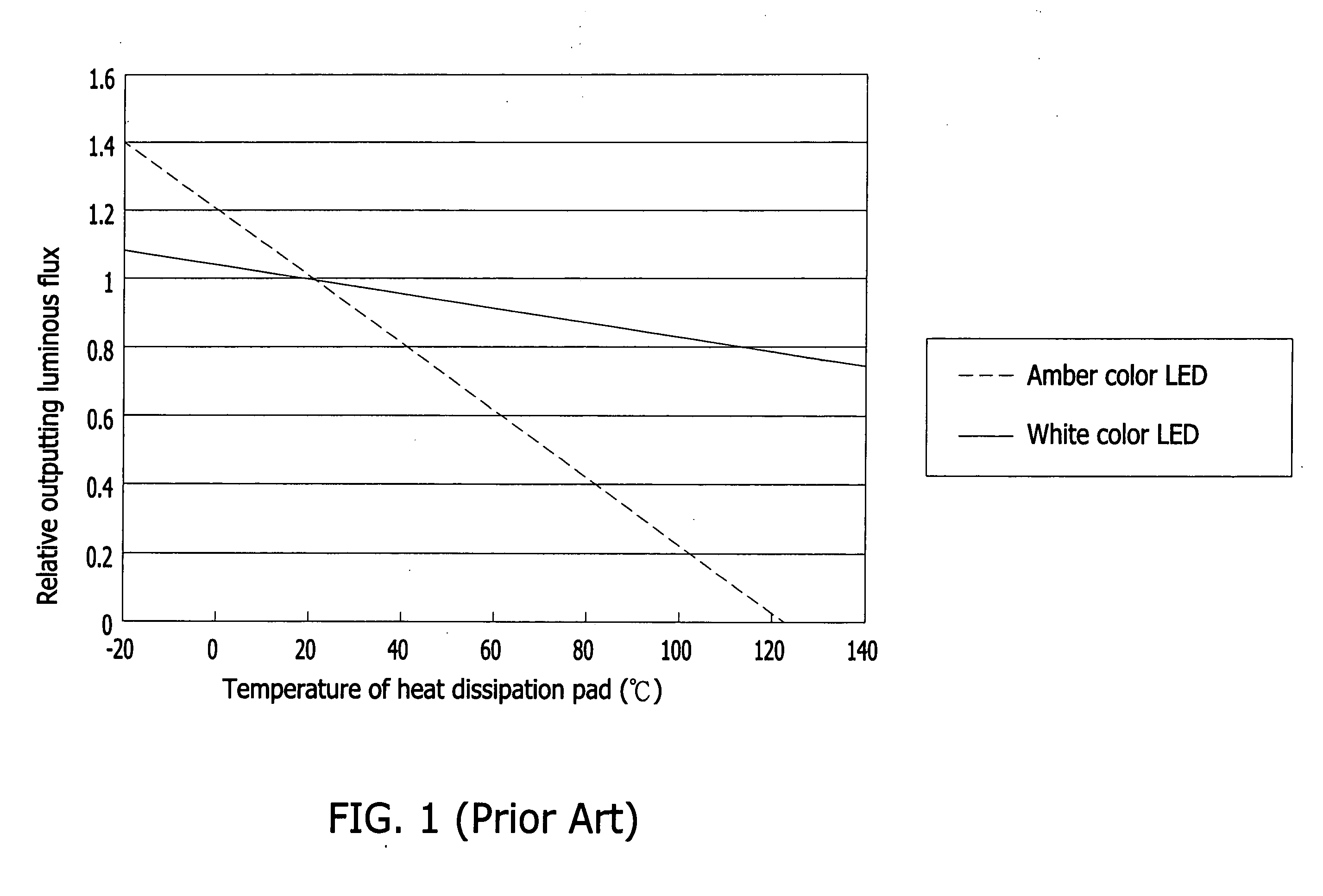
As shown in FIG. 1, the amber color LED is easier to be influenced by temperature than the white color LED, that is, when the temperature of the amber color LED is rising according to the increase of the working time of the amber color LED, the light intensity of the amber color LED may decrease greater than the light intensity of the white color LED, and this may not satisfy users' requirement for the light intensity.
Furthermore, when the white color LED and the amber color LED are disposed on the same heat dissipation pad, the ratio of the luminance of the amber color LED and the ratio of the luminance of the white color LED may become smaller according to the increase of the working time, and this causes a light color change of the white color LED and the amber color LED after light mixing.
The .color of the mixed light may not satisfy the users' requirement.
Besides, since the light emitted from the LED has good directive property, the light source may be over-concentrate.
When the LED is used for the indoor illumination or the outdoor illumination, the over-concentrate light source may cause glare and make people uncomfortable.

Method used


Image

  • Light source apparatus
  • Light source apparatus
  • Light source apparatus

Examples


Embodiment Construction

[0026]In the following detailed description of the preferred embodiments, reference is made to the accompanying drawings which form a part hereof, and in which are shown by way of illustration specific embodiments in which the invention may be practiced. In this regard, directional terminology, such as “top,”“bottom,”“front,”“back,” etc., is used with reference to the orientation of the Figure(s) being described. The components of the present invention can be positioned in a number of different orientations. As such, the directional terminology is used for purposes of illustration and is in no way limiting. On the other hand, the drawings are only schematic and the sizes of components may be exaggerated for clarity. It is to be understood that other embodiments may be utilized and structural changes may be made without departing from the scope of the present invention. Also, it is to be understood that the phraseology and terminology used herein are for the purpose of description an...


PUM


Abstract

A light source apparatus including a first heat transfer element, a second heat transfer element, at least one first light emitting element, and at least one second light emitting element is provided. The first heat transfer element has a first carrying surface and a first heat dissipation surface opposite to the first carrying surface. The second heat transfer element surrounds the first heat transfer element and has a second carrying surface and a second heat dissipation surface opposite to the second carrying surface. The thermal resistance of the first heat transfer element is smaller than the thermal resistance of the second heat transfer element. The first and the second light emitting elements are disposed over the first and the second carrying surfaces respectively. The luminance of the first light emitting element is easier to vary with a change of temperature than the luminance of the second light emitting element.

Description

CROSS-REFERENCE TO RELATED APPLICATION[0001]This application claims the priority benefit of Taiwan application serial no. 97148838, filed on Dec. 15, 2008. The entirety of the above-mentioned patent application is hereby incorporated by reference herein and made a part of this specification.BACKGROUND[0002](1) Technical Field[0003]The invention relates to a light source apparatus, and more particularly relates to a light source apparatus with stable luminance and color.[0004](2) Description of the Prior Art[0005]In recent years, since the luminous efficiency of the light emitting diode (LED) increases continuously, a traditional light source is gradually replaced with the LED in many fields. The light emitting phenomenon of the LED does not belong to heating light emitting or discharge light emitting, but belongs to cold light source, so the LED may keep working for 100 thousand hours or greater. Besides, the LED further has advantages of quick response(about 10−9 seconds), small vo...

Claims


Application Information

Patent Timeline
Patent Type & Authority Applications(United States)
IPC IPC(8): F21S4/00
CPCF21V29/02F21Y2101/02F21V29/006F21V29/83F21V29/505F21V29/677F21V29/74F21K9/135F21K9/232F21Y2115/10F21V29/71
Inventor HU, TUNG-CHOULO, WEI-CHENGWANG, CHENG
Owner YOUNG GREEN ENERGY
Why Eureka
Try Eureka