Seismic array towing system

a towing system and seismic array technology, applied in seismology, seismology, instruments, etc., can solve the problems of limited reduction and time-consuming stacking operation of conventional configuration, and achieve the effects of less drag, convenient stacking operation, and more efficient towing

Active Publication Date: 2010-06-17
SERCEL INC
View PDF13 Cites 58 Cited by
  • Summary
  • Abstract
  • Description
  • Claims
  • Application Information

AI Technical Summary

Benefits of technology

[0013]The present invention is directed to a system and method that provides for a marine seismic array that enables more efficient towing, less drag, and easier stacking operations. The preferred embodiment of the present invention has one or more lead-in cables, where each lead-in cable has a first end engaged with a seismic vessel and a second end attached to a seismic streamer, and one or more diverters directly attached to each cable. In embodiments where multiple diverters are attached to the lead-in cables, the diverters are preferably distributed more closely at the second end of the cables than at the stern of said vessel. In other embodiments, the diverters are distributed evenly between the stern of the vessel and the second end of the cable. Also, another embodiment of the present invention has one or more umbilical cables, where each umbilical cable has a first end engaged with a seismic vessel and a second end attached to a seismic source, and one or more diverters directly attached to at least one umbilical cable. That is, one diverter can be attached to more than one umbilical cables or each umbilical cable can have one or more diverters attached.

Problems solved by technology

As such, the stacking operation of the conventional configuration is very time consuming.
Nevertheless, such reduction is limited by the fact that this configuration still must employ some taglines or separation ropes 308 and additional surface reference floats for smaller diverters 302.

Method used


Image

  • Seismic array towing system
  • Seismic array towing system
  • Seismic array towing system

Examples


Embodiment Construction

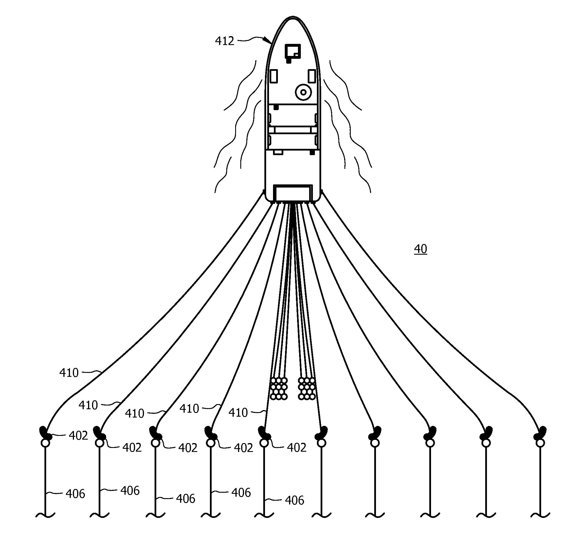
[0073]Turning now to FIG. 4, the port and starboard sides of the preferred embodiment of the present invention are shown as seismic array 40. In the preferred embodiment, at least one wing unit 402 is installed on each lead-in cable 410. As can be seen in FIG. 4, because each lead-in cable 410 has at least one wing unit 402, seismic array 40 eliminates the need for taglines and dedicated towing ropes, thereby reducing the overall drag and fuel consumption. Also, such an arrangement eliminates the handling gear and deck space associated with the paravanes, tow ropes, and separation ropes. Unlike the towing configurations found in the prior art, each wing unit 402 is fastened to its lead-in cable 410 directly. That is, each wing unit 402 is attached to its lead-in cable 410 rather than being tethered via taglines. As such, wing units 402 are preferably completely sub-surface, i.e., fully submerged. In other embodiments, however, it is envisioned that wing units 402 can be at least par...


PUM


Abstract

A system for a more efficient towing of a marine seismic array comprising one or more diverters attached to each lead-in cable. Because each lead-in cable has its own diverter, the need for dedicated towing ropes and taglines between lead-in cables is eliminated, thereby reducing the overall drag and fuel consumption. The diverters of the present invention are directly attached to the respective lead-in cables and are submerged, eliminating the need for taglines and additional flotation. The diverter of the present invention comprises of either a single span-wise hydro foil or two foil sections and is steerable. Similarly, the diverters of the present invention can be installed on the umbilical cables of seismic source subarrays to obtain the same benefits. As such, at least one diverter of the present invention can be attached directly to at least one umbilical cable of the seismic source subarray.

Description

CROSS-REFERENCE TO RELATED APPLICATIONS[0001]This application claims the benefit of U.S. Provisional Application No. 61 / 122,183 filed on Dec. 12, 2008, which is incorporated herein in its entirety.TECHNICAL FIELD[0002]The present disclosure relates generally to marine seismic surveying and, in particular, a method and apparatus for seismic surveying using at least one wing unit, or diverter, per lead-in line, which is an optical-electrical-mechanical towing leader cable, and / or per umbilical cable. More specifically, the present disclosure concerns the attachment of a single or multiple wing units, or diverters, to each lead-in cable to eliminate the need for taglines, dedicated towing ropes, and large paravanes, thereby reducing the overall drag, fuel consumption, and time required to perform stacking operations.BACKGROUND OF THE INVENTION[0003]In seismic surveying, geophysicists direct mechanically generated, low frequency acoustic energy waves into the earth and record the waves ...

Claims


Application Information

Patent Timeline
Patent Type & Authority Applications(United States)
IPC IPC(8): G01V1/38
CPCG01V1/3826
Inventor MARTIN, DANIEL G.
Owner SERCEL INC
Why Eureka
Try Eureka