Hand accessory

a technology for hand accessories and hand muscles, applied in the field of hand accessories, can solve the problems of increased stress on the upper hand, increased weight of the padding, and increased stress on the weaker upper hand, and achieve the effects of avoiding stress or impingement avoiding stress or impinging on the thumb muscle, and reducing the weight of the hand

Inactive Publication Date: 2010-06-17
FROST JOHN H
View PDF15 Cites 0 Cited by
  • Summary
  • Abstract
  • Description
  • Claims
  • Application Information

AI Technical Summary

Benefits of technology

[0028]The main effect of improvements in hand accessory 500 over previous embodiments by the current inventor is the distribution of force from the handle in a greater degree to the tougher, stronger areas which are in the lower hand, and a lesser degree (less stress) in the upper hand, allowing the lower hand to supply more power while the upper hand supplies greater control, lower hand grip 510 channeling greater force through the hand's lower tough ball 39 and upper hand grip 520 confining the remainder of force (stress) to tough, fleshy areas of the web, avoiding stress or impingement to the thumb muscle and the congested area of sensitive joints and tendons between the thumb and fingers.
[0029]Hand accessory 500 (FIGS. 3-14A) improves over embodiment 400 (U.S. Pat. No. 7,431,671) with upper hand grip 520 capturing greater leverage from the web and thumb base and providing protection to the thumb second joint without adding stress to the thumb or any buckling of hand accessory material. An important improvement was the discovery of a means of retaining the leveraging ability of web anchor 418 (now outer web anchor 518) (explained in previous patents) without attachment to lower structure in the area of the hand's lower web 32 and index finger tendon 6, (see FIGS. 7, 8, 9&11) providing an equal amount of protection from bruising to the thumb joint while allowing unrestricted thumb base expansion and downward movement with no stress to the thumb or impingement at the index finger tendon 6. Lower hand grip 510 (previously tough ball anchor 410), with upper apex 501, primary fulcrum point 513, recess junction 503, primary contact extension 543 and anchor flex 572 is a re-designed, more arcing structure, made of thinner material interfacing more efficiently with the hand such that it is less bulky and yet provides better support for handle 48, leveraging handle 48 further outward in the fingers than in embodiment 400 with no impingement or restriction at the hand's fleshy bulge 13 or impingement of the little finger knuckle 27 due to little knuckle phase two angle, or limitation of full phase two range. Upward rotation (see prior explanation) allows primary contact area 506, and a new lower portion, primary contact extension 543 to move into full contact with handle 48 at phase two and then resume an interior position by phase four and the follow-through. Upper hand grip 520 and lower hand grip 510 have been successfully joined in a lower area of the hand than that found in embodiment 400, thereby reducing stress to the upper hand, dispersing stress more evenly over a broader range in the lower hand, bridging over the sensitive mid-palm (with added support of fleshy thumb base relocation from a redesigned upper anchor), and most importantly, allowing the area of the hand inward of the transverse crease 10 and 11 to move fully downward and outward in the important phase two stage of the grip.
[0030]Note: It is not so much the joining in a lower area which reduces the upper hand stress however, as it is the structure itself which allows for the lower joining (explained in the detail). In fact, although previous upper and lower hand anchors could be structurally separate and held in position by a glove, the stability of current lower hand grip 510 and upper hand grip 520 has increased to the extent that separate mounting (see embodiment 500D, FIGS. 9 & 10) is now the preferred embodiment.

Problems solved by technology

The inventor's prior two patents explained the problem of bulkiness in the upper hand / web area: although many forms of padding may serve to protect the thumb from bruising, the bulkiness created by the padding also receives and creates more stress in the weaker upper hand as well as discomfort in the gripping process.
Embodiment 400, used in games by some professional baseball players, was difficult to improve upon.
It provided adequate thumb joint protection and had perfect comfort and bat control in the initial gripping position (phase one) and good control in the ending position (phase three / four), but did not conform perfectly to the hand's “tuck” movement in phase two, and was not widely accepted for bottom hand usage.
An ongoing problem has been bulkiness in the web area not only adding stress to the upper hand at the wrist, but also impinging on the middle and index finger tendons as the thumb base moves downward, as well as stress on the thumb's second joint, third joint (carpal area) and thumb base muscles.
However, neither 203 nor 300 provided adequate protection of the thumb from bruising.
Another problem with previous embodiments was stabilizing the primary contact area 506 against the inertial force of a bat being swung (hand parallel to the ground, bottom of the hand leading), forcing the hand accessory upwards in the hand.
At the end of phase three, there is little space left for any hand accessory material, which creates a challenge in finding a means of insulating the thumb from bruising.

Method used


Image

  • Hand accessory
  • Hand accessory
  • Hand accessory

Examples


embodiment 400

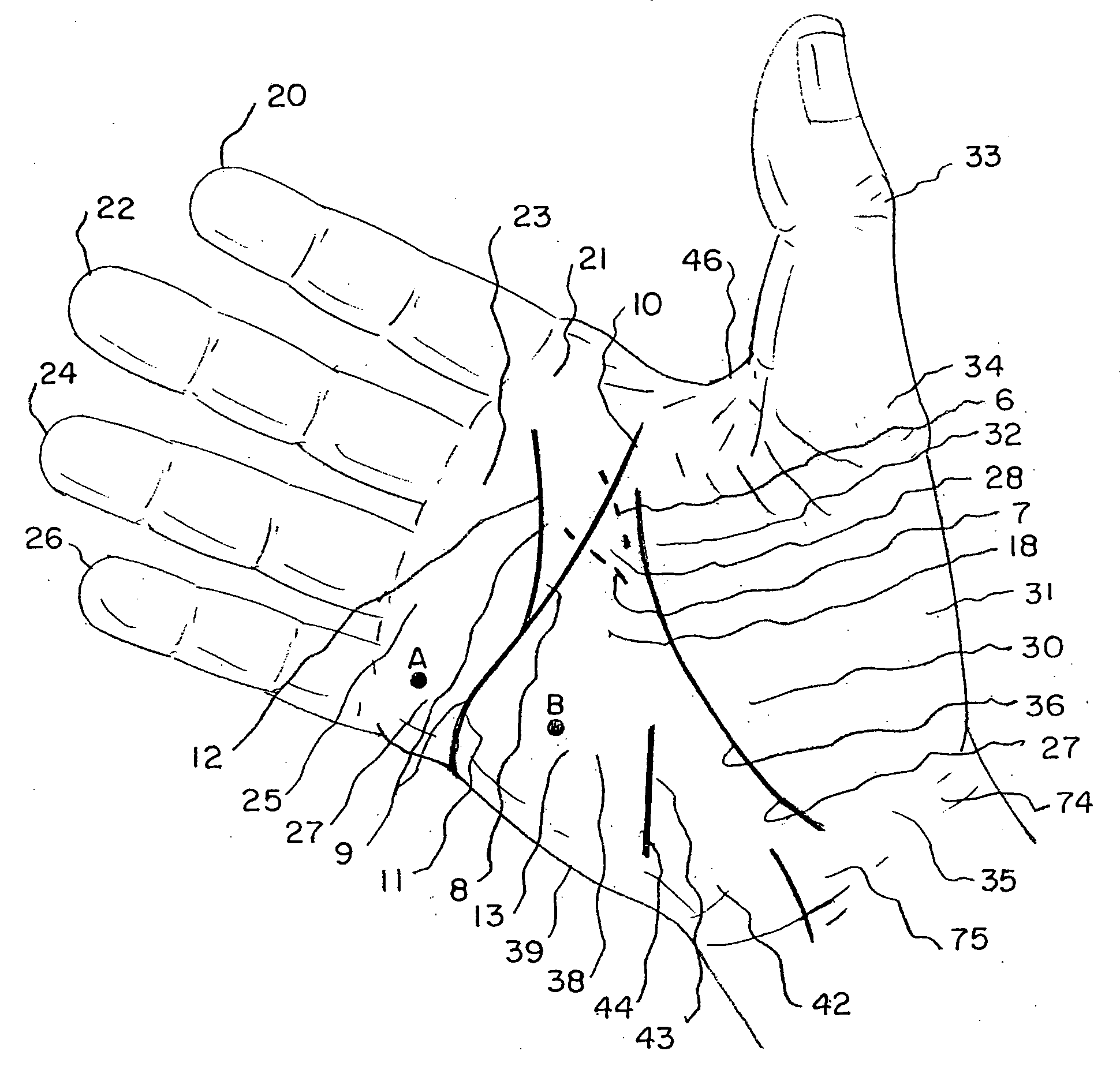
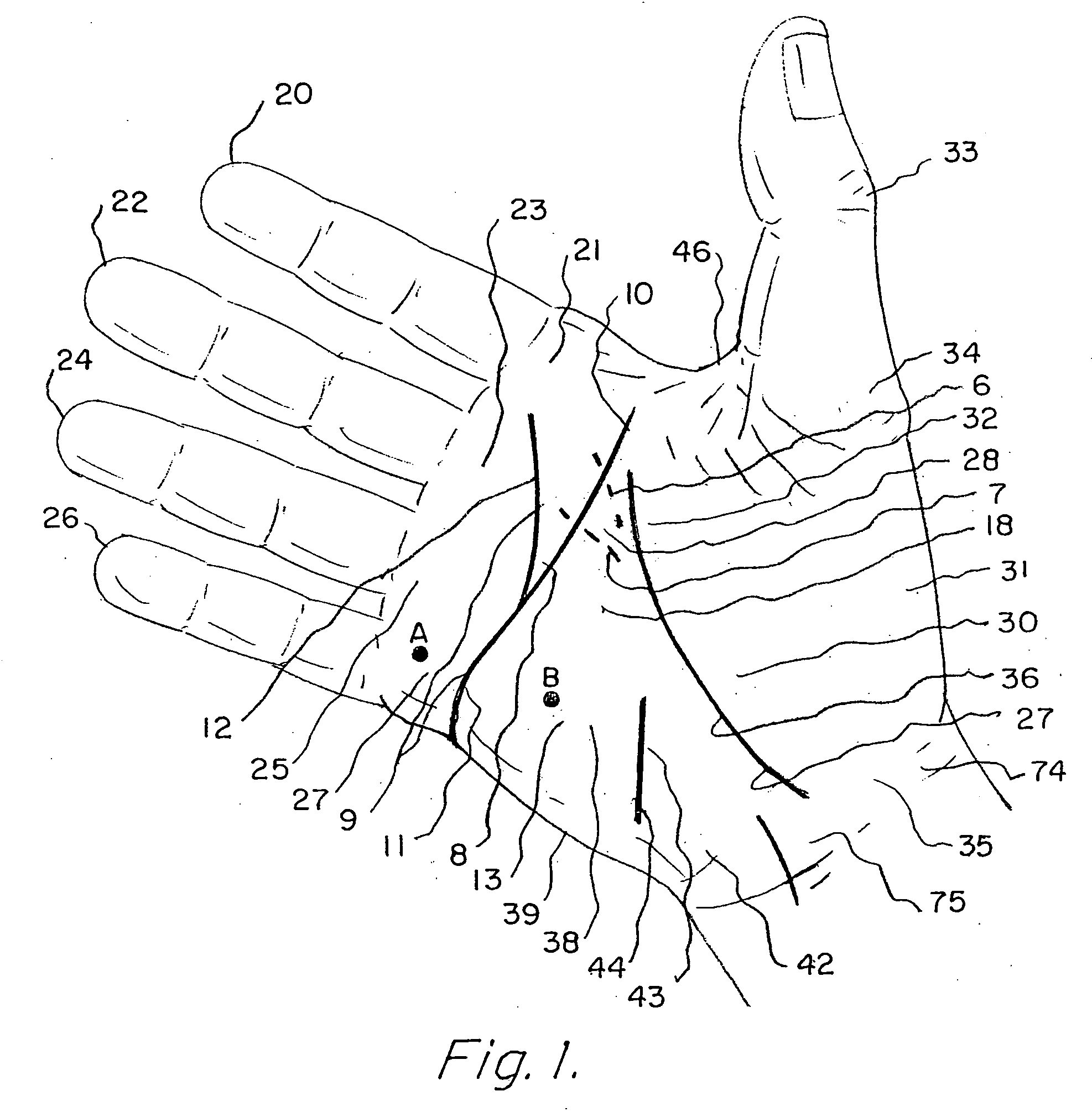
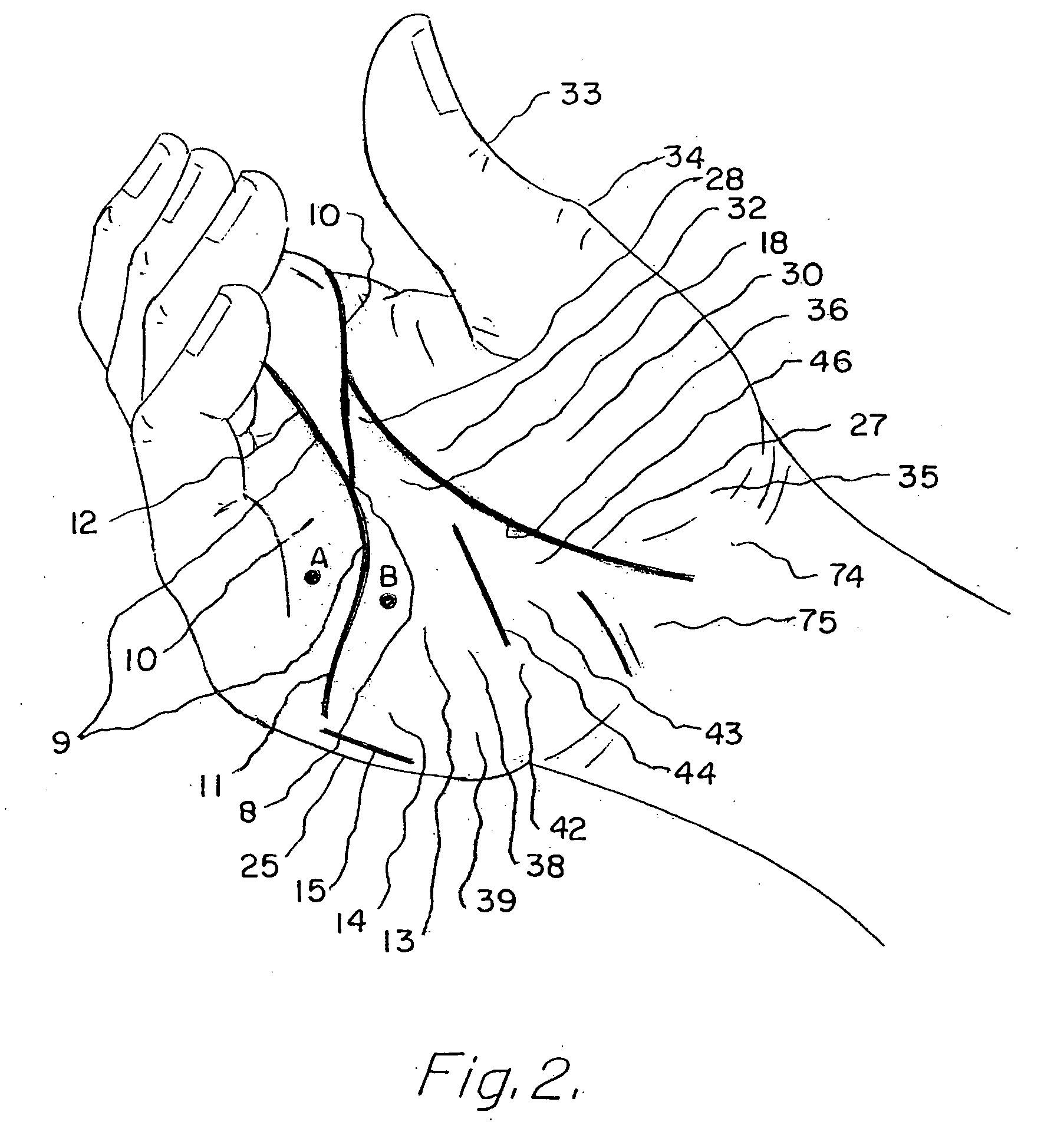
[0048]There is an area within the hand which acts as a fault line, allowing portions on either side to move in opposite directions (like a loose hinge). In embodiment 400 the line was referred to as a transverse crease running from the inside of the little finger knuckle 27 upward to the top of the hand. This area is important in understanding the gripping motion and will be further named and analyzed as follows: Lower transverse crease 11 extends from the inside of little finger knuckle 27 at the bottom of the hand to ring finger hollow 8, thence becoming outer transverse crease 12 branching (as a “Y”) to intersect middle finger 22 and index finger 20. That area acts like a fault line, being the greatest area of movement or “shifting” during phase two of the grip. The portion extending from ring finger hollow 8 upward to the inside of index finger knuckle 21 bordering upper web 46 being upper transverse crease 10. The “fault line” area, the line extending from the base of lower tra...

embodiment 500b

[0057]Embodiment 500B seen in FIGS. 5 & 6 describes by comparison, a much wider and encompassing thumb harness 554 extending to somewhat overlap thumb buffer 548 during certain phases of the grip, (FIG. 6), then angles outwardly to junction 530 such that the inner hand space 5 of 500A is now reduced to upper space 2 and lower space 3.

[0058]The phase two relocation channel 570 of 500B is deepened further, not only by the extension of handle wedge 505, but by bridge 540 and primary contact area 506 arcing further externally and downwardly creating handle space 512 below the hand's lower tough ball and also conforming with little knuckle phase two position.

[0059]Thus, 500B upper hand grip 520 and lower hand grip 510 are similar to embodiment 500A, however the two anchors are joined by a thin, narrow swivel 515 of basically no length, swivel 515 being the uppermost portion of junction 530. The upper and outermost portion of junction 530 presses into ring finger hollow 8 as ring finger f...

embodiment 500c (figs.7-8)

[0070]Embodiment 500C (FIGS. 7-8) is the same as embodiment 500B, with a separation below outer web anchor 518 just above thumb spread 526, which becomes an extended thumb spread 526 functioning as a combined thumb spread 526 and lower web relocation press 519. The upper portion of lower web relocation press 519 combined with deflector 509 and outer web anchor 518 is free to lift externally and outward of index tendon 6 providing more space for the hand's upper web moving downwardly as the thumb moves forward especially during phase three and four, embodiment 500C providing added flexibility and comfort eliminating stress at the thumb muscle and third joint, and leading to embodiment 500D, wherein outer web anchor 518 is separate from thumb spread 526 and deflector 509, deflector 509 and thumb harness 554 becoming more as one body (see following.

[0071]Embodiment 500D (FIGS. 4&9-14A) consists of two structures, lower hand grip 510 in the lower hand, and upper hand grip 520 in the upp...


PUM


Abstract

A hand accessory designed to harness power from strong areas of the hand and channel stress away from weaker areas by means of anchors pressing into tough fleshy areas with connecting structure capable of leveraging a handle away from sensitive bony areas, relocating fleshy areas into supporting and insulating positions, preventing bone bruises and widening the effective grip of the hand for greater control while augmenting the hand's range of motion especially in swinging a baseball bat.

Description

BACKGROUND OF THE INVENTION [0001]1. Field of the Invention[0002]The field of this invention relates generally to hand accessories useful for improving the control and gripping strength of the hand in connection with the handle of an implement, such as a baseball bat, thereby reducing stress to the hand and providing greater control of the handle. More specifically, the current invention distributes force from a recoiling or heavy handle in varying degrees to various areas of the hand in accordance with the suitability of those areas in absorbing force, and / or transferring force to a handle, thus stronger areas of the hand are utilized than would be possible without the invention.[0003]2. Description of the Prior Art[0004]The subject matter of the present invention is an improvement over the structure defined within U.S. Pat. No. 7,179,180 B1 filed Apr. 26, 2005 and U.S. Pat. No. 7,431,671 filed Mar. 10, 2006, invented by the present inventor and designed to enhance the user's gripp...

Claims


Application Information

Patent Timeline
Patent Type & Authority Applications(United States)
IPC IPC(8): A63B69/00
CPCA63B21/1434A63B2069/0008A63B23/16A63B21/4017
Inventor FROST, JOHN H.
Owner FROST JOHN H
Why Eureka
Try Eureka