
Atraumatic suction catheter

a suction catheter and traumatic technology, applied in the field of intubated patient medical care, can solve the problems of tracheobronchial passage trauma, open clogging, and continued problems of suction catheters,

Inactive Publication Date: 2010-06-17
KIMBERLY-CLARK WORLDWIDE INC
View PDF2 Cites 14 Cited by
  • Summary
  • Abstract
  • Description
  • Claims
  • Application Information

AI Technical Summary

Problems solved by technology

These suction catheters, however, have continued to present problems.
When few openings are provided adjacent the distal end, these openings can easily become clogged when high viscosity secretions are suctioned.
The increased suction at the distal tip opening can result in trauma to the delicate tissue of the tracheobronchial passages when the tissue of these passages is pulled against the tip during suctioning.
However, in this instance, the plurality of openings may act more like strainers, resulting in multiple blockages, resulting in the same result previously noted.
Alternatively, however, a large number of openings near the distal tip of the catheter weakens the structure of near the distal tip.
This results in the catheter tip buckling and folding over on itself, such that suctioning is again ineffective or impossible to perform, due the structural failure of the tip of the suction catheter.
Furthermore, when a suction catheter is stiff and has only a few openings at or near the distal tip, the suction catheter may cause impact injury to the delicate tracheobronchial tissue upon insertion against such tissue.
Therefore, these catheters can be advanced only with great caution by the health care provider, and may be ineffective at suctioning due less insertion into the respiratory tract of an intubated patient.

Method used


Image

  • Atraumatic suction catheter
  • Atraumatic suction catheter
  • Atraumatic suction catheter

Examples


Embodiment Construction

[0037]Reference will now be made in detail to one or more embodiments of the invention, examples of the invention, examples of which are illustrated in the drawings. Each example and embodiment is provided by way of explanation of the invention, and is not meant as a limitation of the invention. For example, features illustrated or described as part of one embodiment may be used with another embodiment to yield still a further embodiment. It is intended that the invention include these and other modifications and variations as coming within the scope and spirit of the invention.

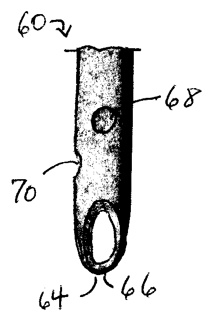
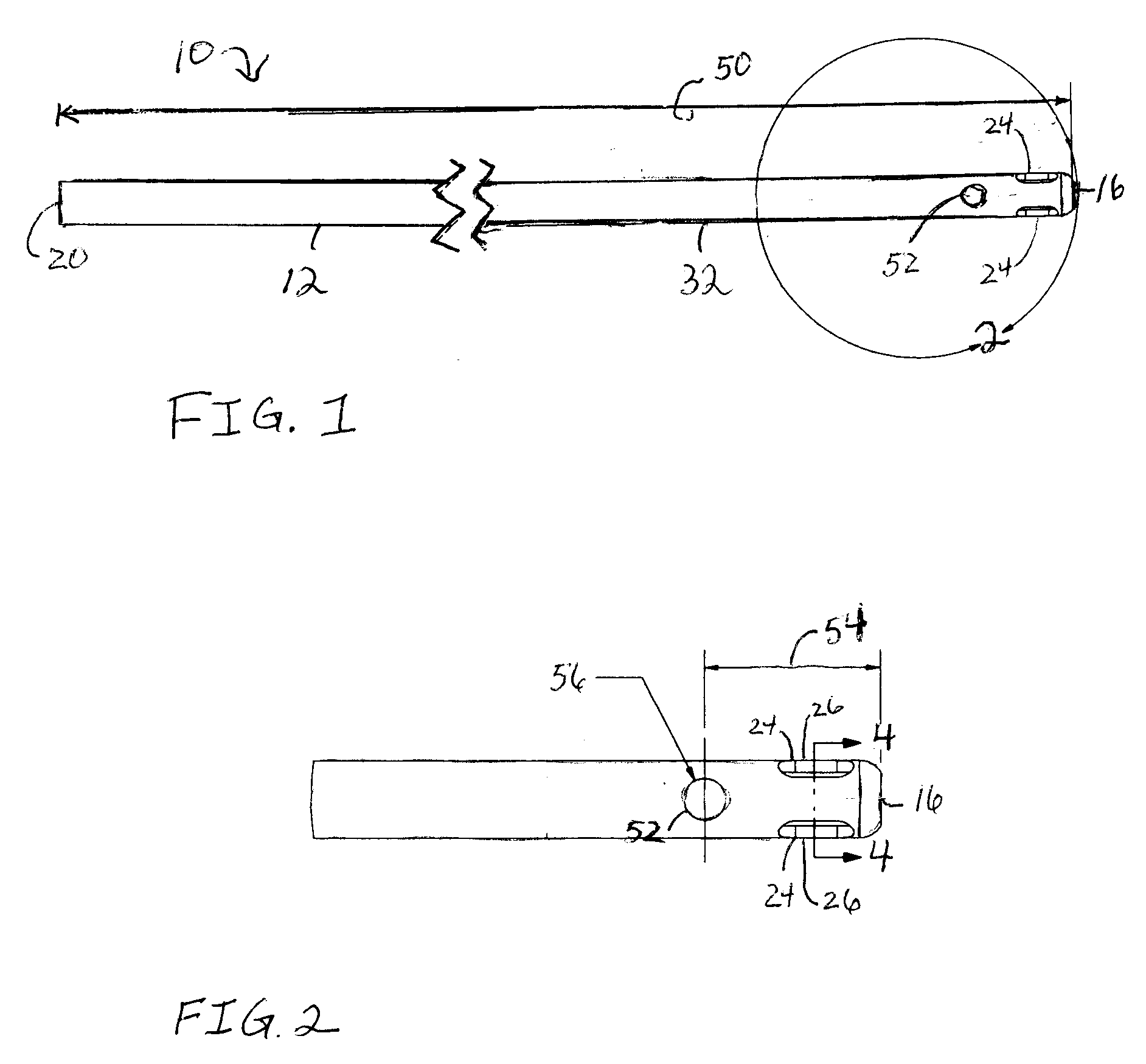
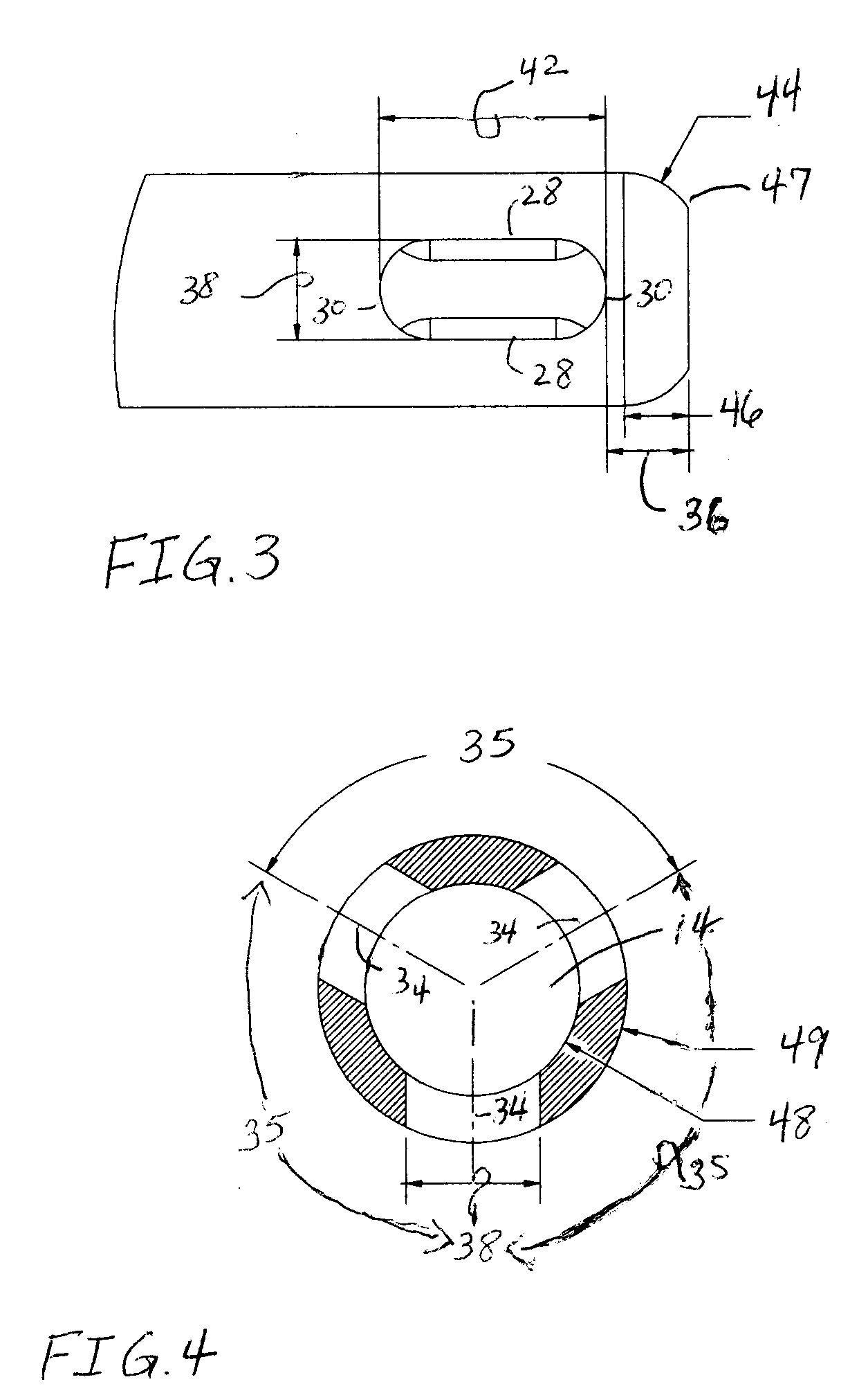
[0038]Turning now to the drawings, as illustrated in FIGS. 1-4 and 5A-C, an atraumatic suction catheter 10 is provided. The suction catheter 10 includes an elongated body 12 having an opening or lumen 14 provided therethrough. A distal end or tip 16 is beveled or formed to have a continuous radius, and has an opening 18 formed therein in communication with the lumen 14. An opposite, proximal end 20 has an ope...


PUM


Abstract

An atraumatic suction catheter having a tubular body with a lumen formed therethrough. At a distal end, the catheter has three equally spaced elongated openings positioned near its distal tip. The catheter may have a fourth round opening positioned proximally to the three openings. The catheter has improved suctioning ability of viscous secretions, and reduced impact compared to other suction catheter embodiments.

Description

BACKGROUND[0001]The invention(s) disclosed herein relate generally to improved medical care for intubated patients, and more particularly to a novel suction catheter for aspiration of mucous and other fluids and secretions from at least a portion of a patient's respiratory tract, namely, the tracheobronchial passages. More particularly, the invention(s) disclosed here relate to suction catheters having improved tip structures which allow for more efficient suctioning of the tracheobronchial passages, while reducing the likelihood of trauma thereto during the suctioning procedure.[0002]Traditionally, suction catheters have consisted of a flexible plastic tube having a lumen formed therethrough. Such suction catheters usually have a beveled distal end or tip with an opening formed in the end which is in axial alignment with the lumen of the catheter. A proximal end of the catheter is configured to connect to a suction vacuum.[0003]Additional openings may be provided adjacent to the di...

Claims


Application Information

Patent Timeline
Patent Type & Authority Applications(United States)
IPC IPC(8): A61M1/00
CPCA61M16/0463A61M1/008A61M16/0484A61M1/84
Inventor MORRIS, CASSANDRA E.BREWER, JOHNREICHART, EMILY
Owner KIMBERLY-CLARK WORLDWIDE INC
Learn More