Aspiration catheter having an internal vacuum accumulator

a vacuum accumulation and catheter technology, applied in the field of catheters, can solve the problems of reducing the amount of suction developed at the distal tip from that applied, presenting significant medical risks, and reducing the distal tip suction amount, so as to avoid pressure loss and increase the dislodging force

Active Publication Date: 2011-05-17
MEDTRONIC VASCULAR INC
View PDF15 Cites 74 Cited by
  • Summary
  • Abstract
  • Description
  • Claims
  • Application Information

AI Technical Summary

Benefits of technology

[0006]In accordance with the invention, aspiration catheters are provided in which an aspirating force is developed within a small chamber in immediate proximity to the distal end of the catheter. In some embodiments the catheter has a lumen, at least at its distal end, in which a short chamber, in the form of a small distal volume of the lumen, is isolated from more proximal portions of the catheter. A sudden pulse of negative pressure is developed within the small volume. By confining the reduced pressure to a small volume at the distal end of the catheter, the invention avoids pressure losses that otherwise may occur when the suction is developed over the full length of the catheter. The confined volume of reduced pressure is exposed, suddenly, to the material to be aspirated. The sudden exposure of a clot or other intravascular matter to the reduced pressure may create a dislodging force that also draws the matter into the chamber and is believed to have increased dislodging force for adherent material, such as thrombus that may be attached to the vessel wall.
[0008]In another embodiment of the invention, the distal chamber includes, at its proximal end, a valved side port in the wall of the catheter that communicates with an aspiration lumen separate from the lumen that defines the distal chamber, and which extends to the proximal end of the catheter. The port is arranged such that it is closed by the piston until the piston has been drawn proximally during its pressure reduction stage sufficiently to expose the side port. The port provides a means by which intravascular matter dislodged and ingested into the chamber by the rapid retraction of the piston then can be aspirated through the port and the aspiration lumen. In this embodiment, the piston can be re-advanced to the distal end of the catheter, closing off the side port and in readiness to effect another cycle of operation.

Problems solved by technology

The existence of such thrombotic material in the vessel may present significant medical risk if the clot migrates downstream with the blood flow.
Among the difficulties that may be encountered in the use of an aspiration catheter is that the amount of suction developed at the distal tip is diminished from that applied at the proximal end of the aspiration lumen as a result of fluid resistance associated with fluid flow through the length of the catheter.
The loss of suction may be especially problematic when trying to dislodge and aspirate intravascular material such as a blood clot, particularly a mature clot that has adhered to the inner vascular wall and may resist aspiration.

Method used


Image

  • Aspiration catheter having an internal vacuum accumulator
  • Aspiration catheter having an internal vacuum accumulator
  • Aspiration catheter having an internal vacuum accumulator

Examples


Embodiment Construction

[0024]Specific embodiments of the present invention are now described with reference to the figures, wherein like reference numbers indicate identical or functionally similar elements. The terms “distal” and “proximal” are used in the following description with respect to a position or direction relative to the treating clinician. “Distal” or “distally” are a position distant from or in a direction away from the clinician. “Proximal” and “proximally” are a position near or in a direction toward the clinician.

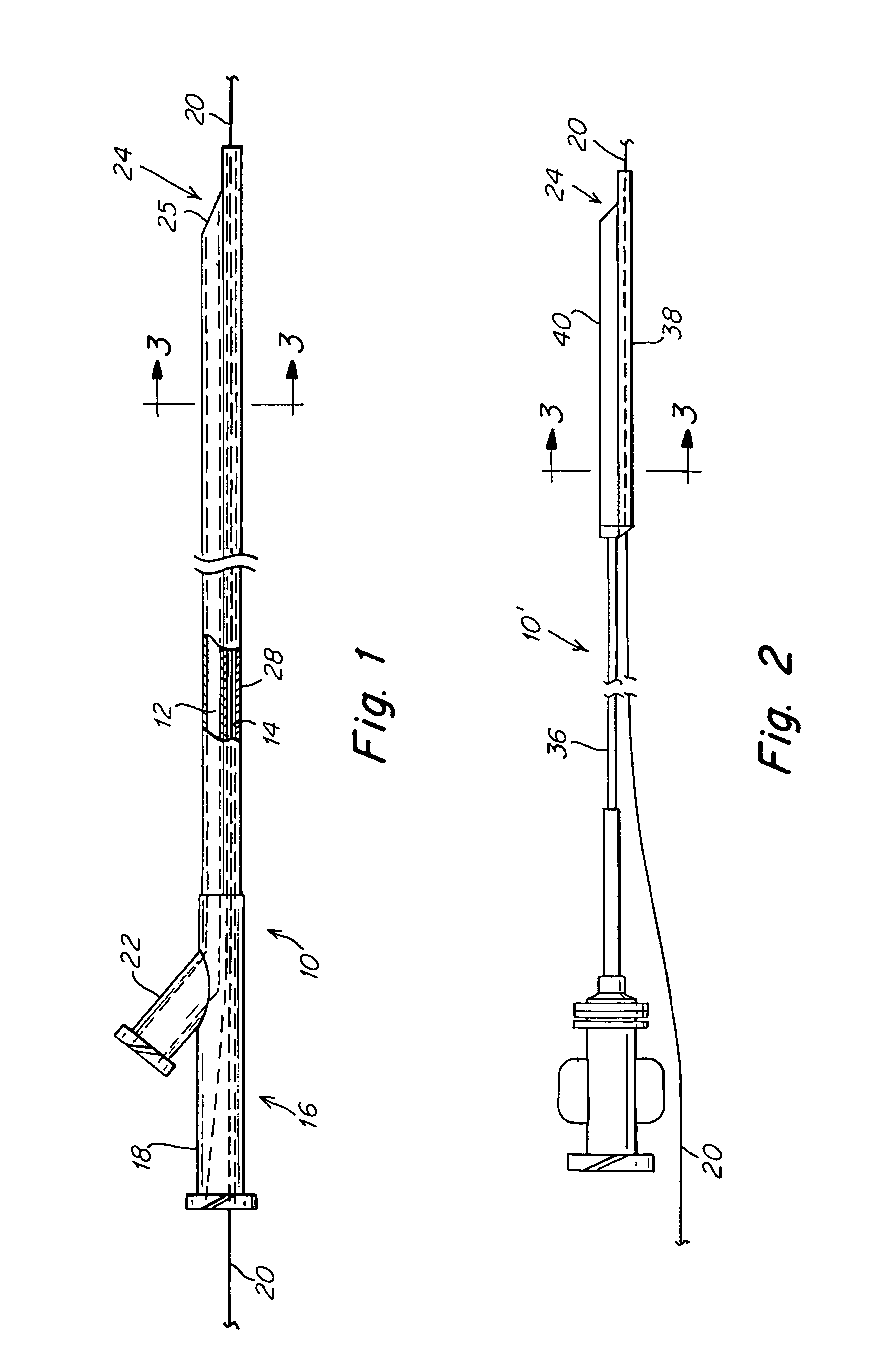
[0025]FIG. 1 illustrates, somewhat diagrammatically, a two-lumen, elongate catheter 10 having an aspiration lumen 12 and a guidewire lumen 14. Both lumens may extend substantially the full length of the catheter, although in some embodiments the aspiration lumen may be limited to the distal region of the catheter. The proximal ends of the lumens may terminate in a Y-fitting 16, one leg 18 of which receives a guidewire 20 and the other leg 22 communicates with the aspiration lume...


PUM


Abstract

An aspiration catheter is provided in which vacuum may be accumulated within the catheter and released suddenly within a distal region of the catheter to induce ingestion of intravascular matter into the catheter through an open distal port while avoiding large losses of suction common with catheters having long aspiration lumens. Conventional aspiration using the same catheter can subsequently complement the procedure by fully removing the ingested matter from the catheter.

Description

FIELD OF THE INVENTION[0001]The invention relates to aspiration catheters for removal from a blood vessel of thrombotic, atherosclerotic or particulate matter, whether it is adherent to the wall of the blood vessel or suspended in the blood.BACKGROUND OF THE INVENTION[0002]Aspiration catheters are used commonly in connection with interventional vascular procedures such as angioplasty, atherectomy, stent placement, and the like to aspirate debris that may result from an interventional procedure. They also are useful in removing thrombus (clot masses) that may be present in a blood vessel before the interventional catheterization procedure is initiated and also are used to remove clots whether or not other intravascular procedures are intended or have been performed. Such procedures are referred to as aspiration thrombectomy or aspiration embolectomy. The existence of such thrombotic material in the vessel may present significant medical risk if the clot migrates downstream with the b...

Claims


Application Information

Patent Timeline
Patent Type & Authority Patents(United States)
IPC IPC(8): A61M1/00
CPCA61B17/22A61B2017/22039A61M1/0031A61B2217/005A61B2017/22079A61M1/74
Inventor MAS, JUAN-PABLOCANGIALOSI, VINCENT J.
Owner MEDTRONIC VASCULAR INC
Why Eureka
Try Eureka