Injector with throttle variable nozzle and injector circulation using such injector

A technology of ejector and throttle valve, applied in the direction of fluid circulation arrangement, irreversible circulation compressor, jet pump, etc., can solve problems such as destroying the efficiency of the nozzle

Inactive Publication Date: 2004-05-26
DENSO CORP
View PDF0 Cites 18 Cited by
  • Summary
  • Abstract
  • Description
  • Claims
  • Application Information

AI Technical Summary

Problems solved by technology

However, according to the experiments of the inventors of the present invention, simply changing

Method used


Image

  • Injector with throttle variable nozzle and injector circulation using such injector
  • Injector with throttle variable nozzle and injector circulation using such injector
  • Injector with throttle variable nozzle and injector circulation using such injector

Examples


no. 1 example

[0025] The injector of the embodiment related to the present invention is generally used in the injector cycle of a vehicle air conditioner.

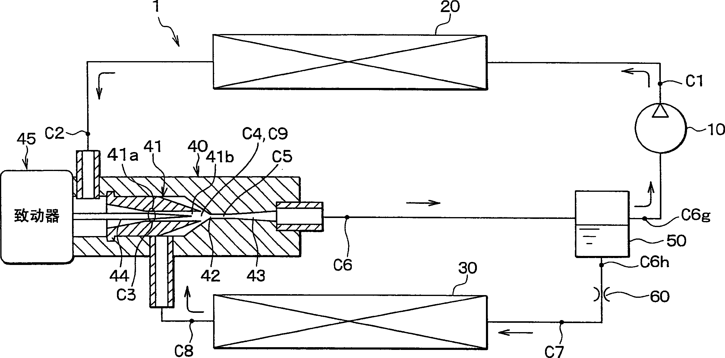
[0026] figure 1 A schematic diagram of an ejector cycle 1 using carbon dioxide as refrigerant is shown. The compressor 10 is a variable displacement compressor for sucking and compressing refrigerant, and is driven by a vehicle engine to operate. The discharge amount of the compressor 10 is controlled so that the temperature or pressure in the evaporator 30 (described later) is controlled within a predetermined range.

[0027] The radiator 20 is a high-pressure side heat exchanger that cools the refrigerant by performing heat exchange between the refrigerant discharged from the compressor 10 and the outside air (ie, the air outside the passenger compartment). The evaporator 30 is a low-pressure side heat exchanger that cools the air to be blown toward the passenger compartment while evaporating the liquid refrigerant by performing hea...

no. 2 example

[0045] exist Image 6 In the shown second embodiment, the shape of the inner wall of the throat 41a in the nozzle 41 according to the first embodiment is a curved surface, so that the cross-sectional area of ​​the refrigerant passage changes continuously and smoothly from the refrigerant inlet of the nozzle 41 to the throat. 41a. In this way, generation of eddy currents in the downstream side near the throat portion 41a can be reduced, so that losses such as eddy current losses and the like can be reduced. As a result, nozzle efficiency can be further increased. In the second embodiment, other parts are similar to those of the first embodiment described above.

no. 3 example

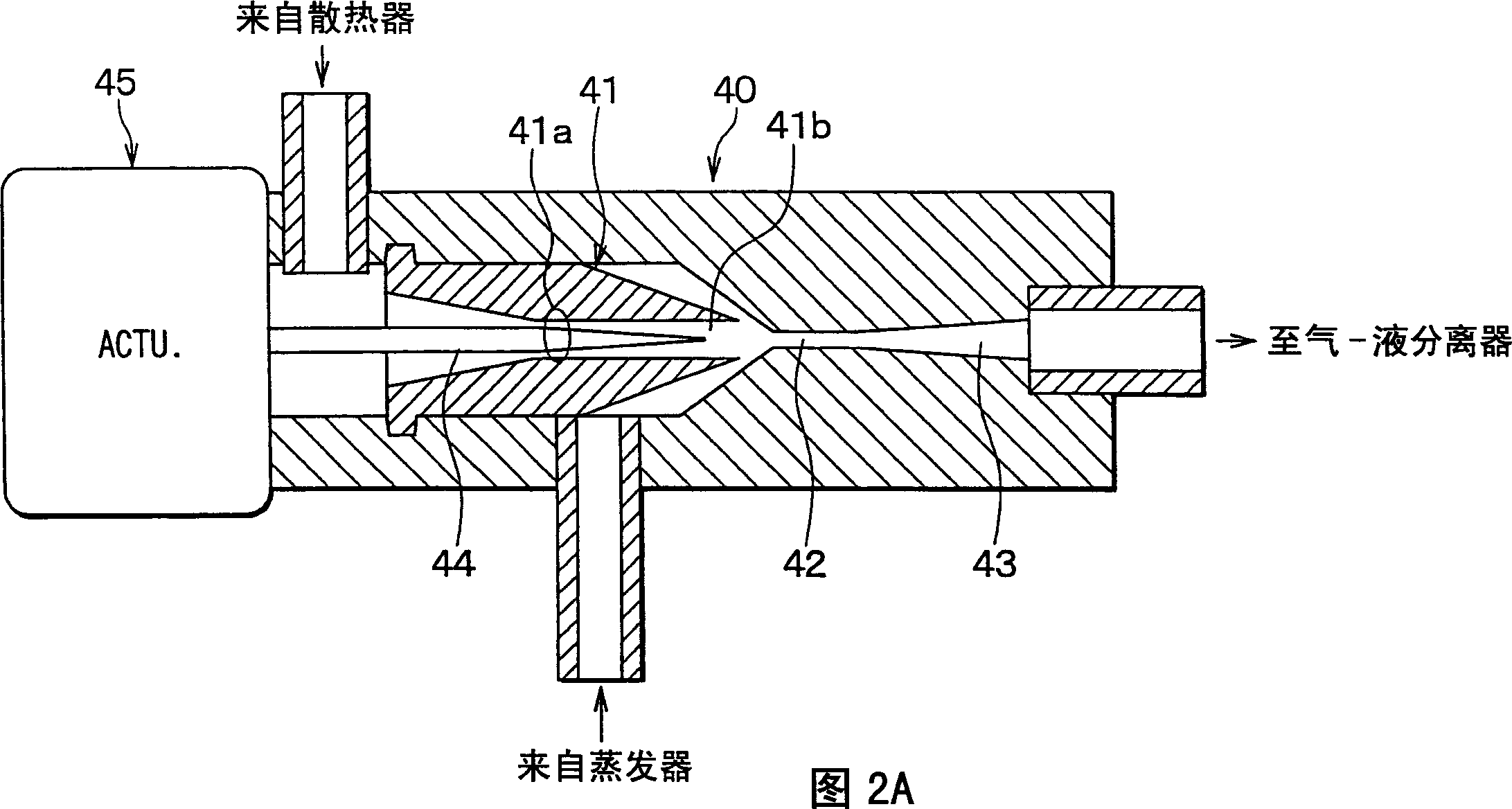
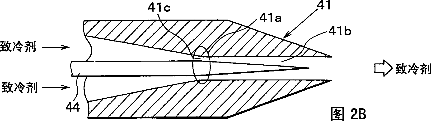
[0047] In the above-described first embodiment of the present invention, the cross-sectional area of ​​the refrigerant passage from the refrigerant inlet of the nozzle 41 to the throat 41a gradually decreases by a constant cone angle. However, in this example, if Figure 7 As shown, the cone angle θ1 on the throat 41 a side of the nozzle 41 is set smaller than the cone angle θ0 on the refrigerant inlet side of the nozzle 41 and the cone angle θ2 at the end of the needle valve 44 . In addition, the needle valve 44 controls the throttle opening degree from the minimum opening degree to the maximum opening degree, while at least the tip of the needle valve 44 is located on the downstream side of the throat portion 41a in the refrigerant flow.

[0048] In this embodiment, the cone angle θ1 of the throat 41a is smaller than the cone angle θ0 of the refrigerant inlet side of the nozzle 41, and the position of the throttle portion 41c is on the upstream side of the refrigerant flow r...


PUM


Abstract

An ejector includes a nozzle and a needle valve formed in a tapered shape. The needle valve controls a throttle opening degree of the nozzle from a minimum degree to a maximum degree while an end section of the needle valve is positioned on a downstream side with respect to a throat section of the nozzle. Besides, a cross-sectional area of a nozzle diffuser is formed to be substantially constant, downstream of the throat section. Thus, a cross-sectional area of a substantial refrigerant passage defined by an inner surface of the nozzle and the needle valve is gradually widened in accordance with the tapered shape of the needle valve. Therefore, pressure loss accompanied with a rapid expanding can be suppressed. As a result, the throttle opening degree of the nozzle can be controlled while improving nozzle efficiency and ejector efficiency.

Description

technical field [0001] The present invention relates to an injector (refer to JIS Z 8126 No. 2.1.2.3) and an injector cycle using the injector, which delivers a fluid using entrainment of a driving fluid injected at a high velocity. The injector has a throttle variable nozzle. Background technique [0002] As is well known, in the ejector cycle, the low-pressure side refrigerant (ie, the refrigerant in the evaporator) is circulated by the suction operation of the ejector. In addition, in the ejector, while the expansion energy is converted into pressure energy, the suction pressure of the refrigerant to be sucked to act on the compressor is increased, so as to reduce the power consumption of the compressor. However, when the energy conversion efficiency in the ejector (ie, ejector efficiency) decreases, the suction pressure of the compressor in the ejector cannot be sufficiently increased, and as a result, the power consumption of the compressor cannot be sufficiently reduc...

Claims


Application Information

Patent Timeline
IPC IPC(8): F04F5/18B05B7/30F04F5/04F04F5/46F04F5/48F25B1/00F25B41/00F25B41/06
CPCF04F5/04F04F5/461F25B41/062F25B2341/0013F25B2341/0653F25B2341/0012F25B2309/061Y02B30/72F25B41/00F25B2500/01B60H2001/3298Y02B30/70F25B41/35
Inventor 川村进酒井猛
Owner DENSO CORP
Why Eureka
Try Eureka