Fan unit for wind power generator and wind power generator

Inactive Publication Date: 2010-05-06
MITSUBISHI HEAVY IND LTD
View PDF12 Cites 17 Cited by
  • Summary
  • Abstract
  • Description
  • Claims
  • Application Information

AI Technical Summary

Benefits of technology

[0027]According to the fan unit for a wind power generator in accordance with the first aspect of the invention and the wind power generator in accordance with the second aspect, a rectification part adjusts distribution

Problems solved by technology

This causes a problem where a pressure loss at an air intake port of the fan or a discharge port of the fan increases according to the internal structure of the nacelle or the placement of the fan, and the ventilation performance and the cooling performance can not be sufficiently exerted.
This causes a problem where a pressure loss at an air flow port of the fan is increased.
In the case where a heat exchanger is mounted to the fan such as with the cooling fa

Method used


Image

  • Fan unit for wind power generator and wind power generator
  • Fan unit for wind power generator and wind power generator
  • Fan unit for wind power generator and wind power generator

Examples


first embodiment

[0054]A wind power generator in accordance with the First Embodiment of the invention will be described hereinafter, with references to FIGS. 1 to 7.

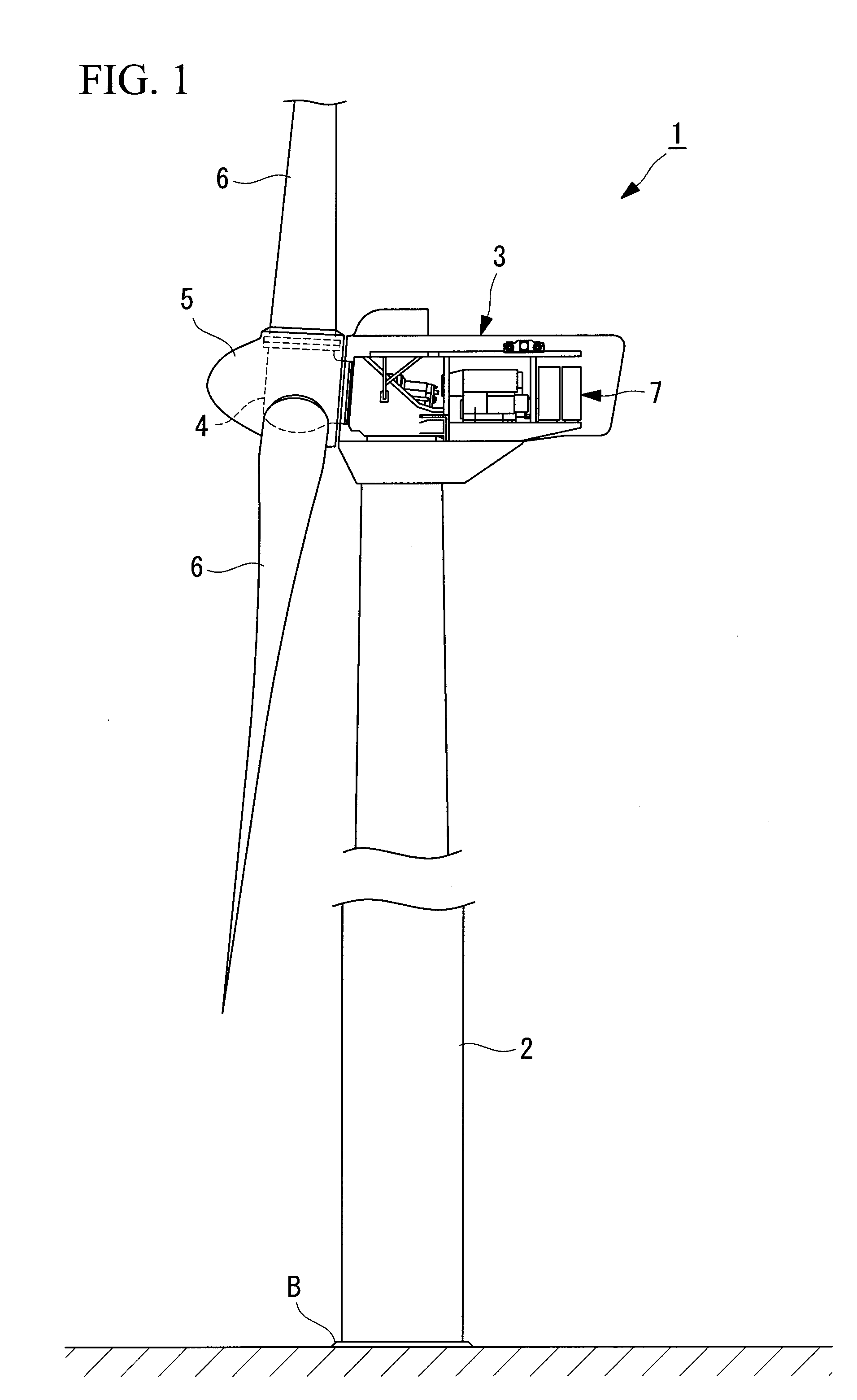
[0055]FIG. 1 illustrates an overall structure of a wind power generator in accordance with First Embodiment.

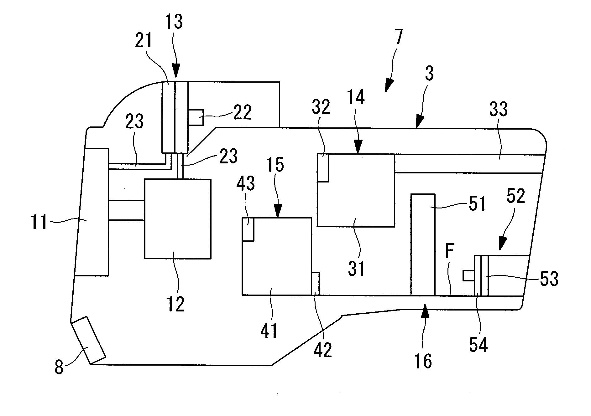
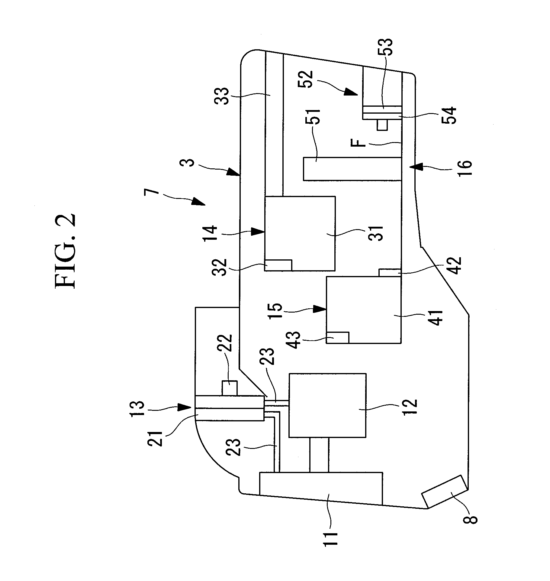
[0056]A wind power generator 1 is for generating wind power, as shown in FIG. 1. The wind power generator 1 comprises a support 2 erected on a base B, a nacelle 3 provided at the top end of the support 2, a rotor head 4 mounted to the nacelle 3 so as to be rotatable about a substantially horizontal axis, a head capsule 5 for covering the rotor head 4, plural windmill rotation vanes 6 radially mounted around the rotation axis of the rotor head 4 and generation devices (equipment) 7 for generating electricity in accordance with a rotation of the rotor head 4.

[0057]In First Embodiment, exemplified will be a case in which three windmill rotation vanes 6 are provided. The number of the windmill rotation vanes 6, however, is not limited...

second embodiment

[0116]Next, Second Embodiment of the invention will be described, with reference to FIGS. 8 to 11.

[0117]A basic structure of the wind power generator in accordance with Second Embodiment is similar to that of First Embodiment. Second Embodiment is different from First Embodiment in the structure of the fan unit for a converter. Accordingly, the structure of the fan unit for a converter will only be described in Second Embodiment with reference to FIGS. 8 to 11. Descriptions of other components and such are omitted.

[0118]FIG. 8 is a simplified view of a structure of a fan unit for a converter in a wind power generator in accordance with Second Embodiment.

[0119]Components same as those of First Embodiment are marked with the same reference signs and numerals and omitted from description.

[0120]A fan unit for a converter 452 in a wind power generator 401 comprises the heat exchanger for a converter 53 for circulating the refrigerant for cooling the converter main body 51, the fan for a ...

third embodiment

[0138]Next, the Third Embodiment of the invention will be described, with reference to FIG. 12.

[0139]A basic structure of the wind power generator in accordance with Third Embodiment is similar to that of First Embodiment. Third Embodiment is different from First Embodiment in the structure of the fan unit for a converter. Accordingly, the structure of the fan unit for a converter will be only described in Third Embodiment with reference to FIG. 12. Descriptions of other components and such are omitted.

[0140]FIG. 12 is a simplified view of a structure of a fan unit for a converter in a wind power generator in accordance with Third Embodiment.

[0141]Components same as those of First Embodiment are marked with the same reference signs and numerals and omitted from description.

[0142]A fan unit for a converter 552 in a wind power generator 501 comprises the heat exchanger for a converter 53 for circulating the refrigerant for cooling the converter main body 51, the fan for a converter 54...


PUM


Abstract

To provide a fan unit for a wind power generator and a wind power generator, which are capable of preventing a loss of a flow at a flow port from increasing and capable of preventing a pressure loss of a heat exchanger from increasing. A fan unit for a wind power generator (52) having an axial fan (54) for discharging air in a nacelle of the wind power generator to a rear side of the nacelle, the axial fan (54) being provided on a floor (F) of the nacelle, and an equipment (51) of the wind power generator provided in front of the axial fan (54) in a direction of a rotation axis (L) is characterized by including a rectification part (56) for adjusting distribution of the flow rate of air flowing into the axial fan (54).

Description

TECHNICAL FIELD [0001]The present invention relates to a fan unit for a wind power generator and a wind power generator.BACKGROUND ART [0002]The range of air temperatures in which the wind power generator is operated is generally from minus 30 degrees centigrade to plus 40 degrees centigrade. Accordingly, it is necessary to control the temperature of the internal equipment of the wind power generator such as main bearings, a speed increasing gear, a generator, a transformer and an inverter, for example, to within a range of the standard temperature.[0003]In order to perform such temperature control, an oil piping system for a vane pitch system, the speed increasing gear, the main bearing and the like and a cooling piping system for the inverter and the like are respectively provided with heaters and coolers as temperature control systems (refer to Patent Document 1).[0004]The cooler is provided with a cooling fan for ventilating the cooler. Each of the heater and the cooling fan is ...

Claims


Application Information

Patent Timeline
IPC IPC(8): H02P9/04
CPCF04D15/029F04D25/08Y02E10/721F03D13/20F03D80/60F03D9/25Y02E10/726Y02E10/72
Inventor SATO, SHINSUKESATO, TOSHIHIROHIRAI, SHIGETOSHIRAISHI, TATSUYA
Owner MITSUBISHI HEAVY IND LTD
Why Eureka
Try Eureka