Prosthetic implant with biplanar angulation and compound angles

a technology of compound angles and prosthetic implants, applied in the field of prosthetic implants, can solve the problems of poor fixation and potential reoperation, difficult rotational step, and the placement of the cage requires rotation, and achieve the effect of reducing or eliminating the need for rotation

Active Publication Date: 2010-06-17
X SPINE SYST
View PDF43 Cites 102 Cited by
  • Summary
  • Abstract
  • Description
  • Claims
  • Application Information

AI Technical Summary

Benefits of technology

[0013]Still another object of the invention is to provide a cage having a biplanar angulation and that minimizes or eliminates the need for rotation after the cage is inserted into the disk space.

Problems solved by technology

A challenge to the placement of cages is the attainment of proper fitment between the adjacent vertebrae.
If a cage fits poorly, the cage could loosen, causing poor fixation and potential re-operation.
A significant difficulty with banana-type cages is that their placement requires cage rotation at the time of placement to seat the cage in place.
This rotational step is difficult in that it occurs blindly inside the disk space.
Incomplete rotation frequently occurs, resulting in poor cage fitment, with potential loosening and reoperation.
Furthermore, a standard lordotic cage, such as Michelson (U.S. Pat. No. 6,302,914), would have its lordotic angle in the incorrect orientation for proper fitment if placed diagonally.

Method used


Image

  • Prosthetic implant with biplanar angulation and compound angles
  • Prosthetic implant with biplanar angulation and compound angles
  • Prosthetic implant with biplanar angulation and compound angles

Examples


Embodiment Construction

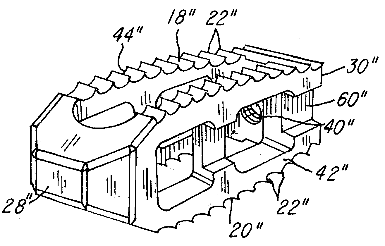
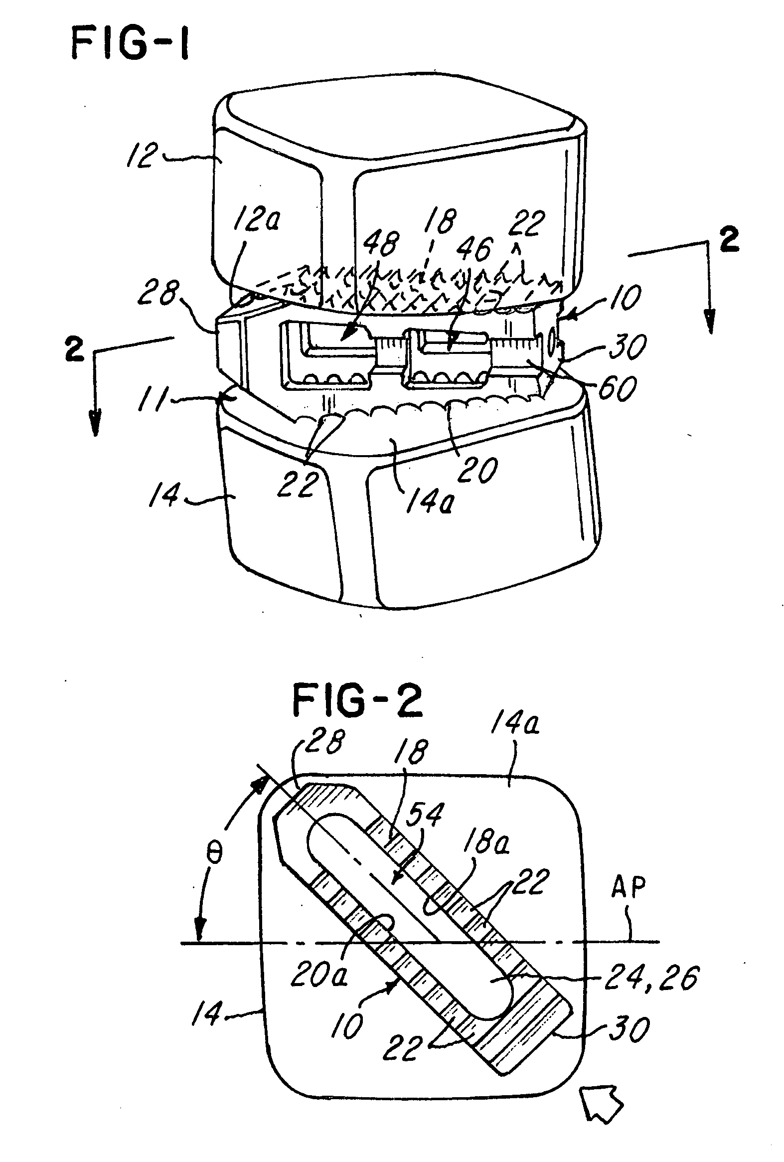
[0051]Referring now to FIGS. 1-10, a prosthetic implant or fusion cage 10 is shown for insertion and use in a disk space or disk area 11 between a first vertebra 12 and second vertebra 14. In the illustration being described, the first vertebra 12 has a first or superior surface 12a and the second vertebra 14 has a second or inferior surface 14a, as best illustrated in FIG. 1. The cage 10 is inserted straight posterolaterally, also called a transforamenal approach, into the disk area 11 between the first vertebra 12 and second vertebra 14. As described and shown, the cage 10 is inserted on a diagonal or angled direction with respect to an anterior-posterior axis AP (FIG. 2), such as in the direction of arrow 16 as shown.

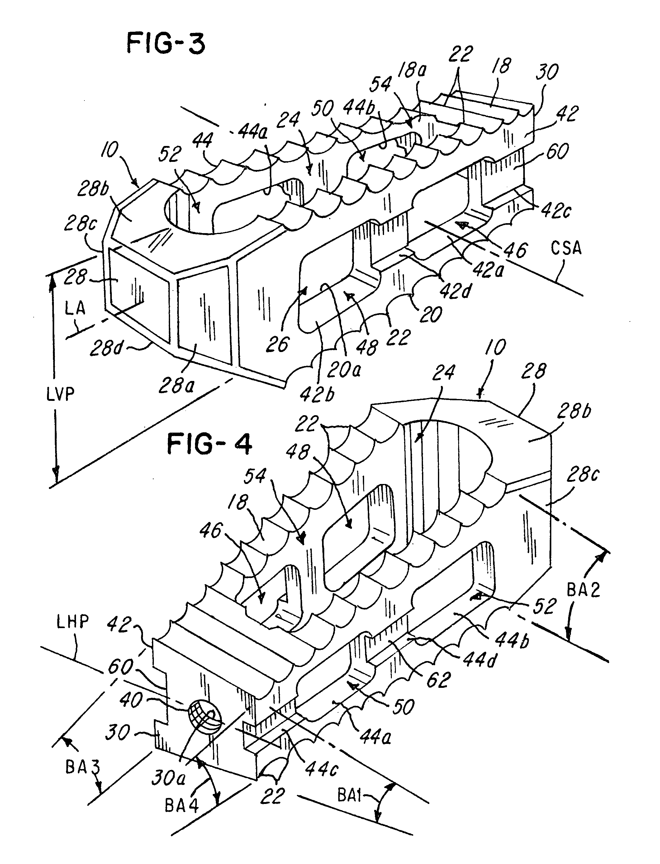
[0052]Notice in FIGS. 3 and 4 that the cage 10 comprises a superior or top surface 18 and a generally opposing inferior or bottom surface 20. In the illustration being described, note that the surfaces 18 and 20 are serrated or comprise teeth 22 to facilitate prevent...


PUM


Abstract

A prosthetic implant, and more particularly, with a prosthetic implant having biplanar angulation and that can be inserted into a disk area generally straight using a posterolateral approach.

Description

BACKGROUND OF THE INVENTION[0001]1. Field of the Invention[0002]This invention relates to a prosthetic implant, and more particularly, with a prosthetic implant having a biplanar angulation to permit insertion straight along a diagonal angle into a disk space.[0003]2. Description of the Related Art[0004]Spinal fusion is a commonly performed procedure. In a typical spinal fusion operation, a surgeon places a mechanical container, commonly known as a cage, between at least two adjacent vertebrae of the spine. This container contains or is later filled with bone graft which eventually incorporates into the adjacent vertebrae and creates a solid fusion. Interbody cages are placed in the disk space following removal of the disk. The cage can be surgically placed via several approaches, such as anteriorly through the abdomen, posteriorly through the spinal canal, posterolaterally through the neuroforamen of the vertebra, and transversely from a side of the spine. A goal of the surgical ap...

Claims


Application Information

Patent Timeline
Patent Type & Authority Applications(United States)
IPC IPC(8): A61F2/44
CPCA61F2/447A61F2/4611A61F2002/2835A61F2002/30616A61F2002/30617A61F2250/0097A61F2002/3082A61F2002/30841A61F2002/30904A61F2002/4629A61F2002/30785
Inventor KIRSCHMAN, DAVID LOUIS
Owner X SPINE SYST
Why Eureka
Try Eureka