Sling clips and attachment

a technology of sling clips and clips, applied in the field of slings, can solve the problems of affecting the decision time, sight acquisition, and the ability of soldiers to be closer to the intended target, and achieve the effect of reducing the movement of the muzzle end and the butt end of the weapon, reducing the need for antagonistic muscle action, and quick raising the weapon

Active Publication Date: 2020-04-28
THOMPSON STEPHEN T
View PDF82 Cites 1 Cited by
  • Summary
  • Abstract
  • Description
  • Claims
  • Application Information

AI Technical Summary

Benefits of technology

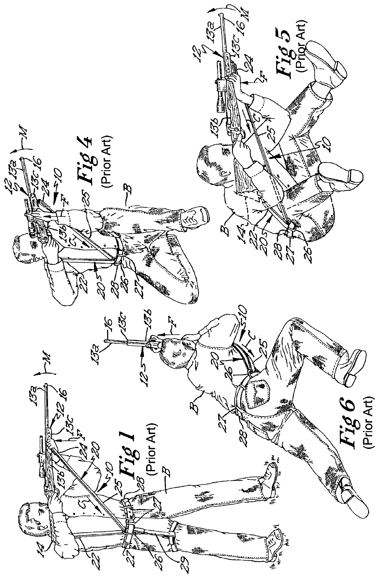
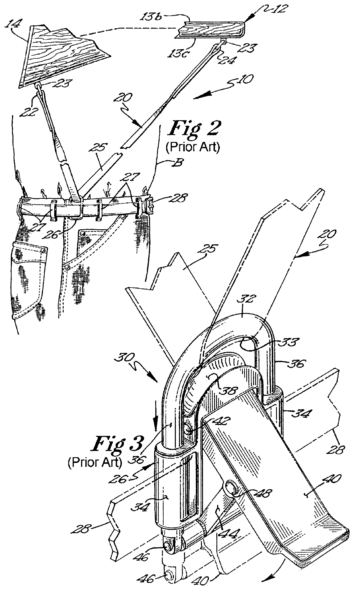
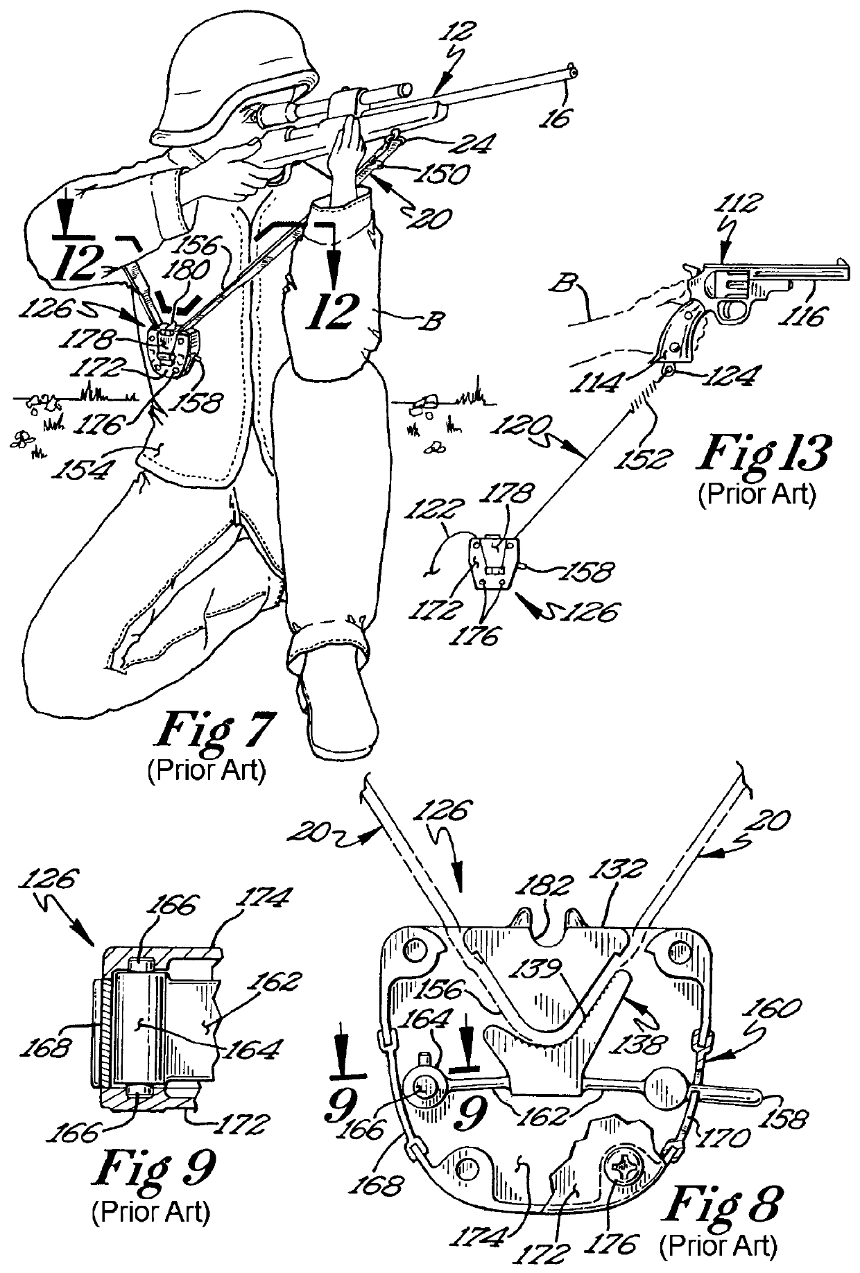
[0021]A sling clip is disclosed that has a clamping mechanism capable of releasably securing the strap when the strap is slidably received through an opening in the sling clip. The sling clip also has an attachment apparatus configured to secure the sling clip proximate to a weapon user's body. The clamping mechanism is operatively configured to secure the strap within the sling clip when the weapon is in a firing position such that the strap minimizes movement of a muzzle end and a butt end of the weapon caused by recoil of the weapon upon firing. The strap also allows the user to rapidly raise the weapon to firing or use position, and minimizes or eliminates the need for antagonistic muscle action to achieve the desired firing position. A weapon sling including the sling clip also is disclosed.

Problems solved by technology

In contrast to shooting from a rest or standard position, moving and shooting results in lost accuracy and effective range.
This results in the soldier having to be closer to the intended target and therefore in greater danger.
Obstacles to accuracy produced by movement include increased area of muzzle wobble, speed of muzzle wobble, and a more erratic type of muzzle wobble, all which adversely affect trigger break, sight acquisition, and decision time.
The machinations of the weapon from firing and moving combine to further decrease accuracy.
A skilled person would possess a high degree of athleticism and trigger control, but undesirably will still be slowed by movement.
One problem common to slings designed to facilitate the transportation of weapons is that there is little thought given to whether or how these slings may be used to stabilize the weapon during firing.
However, this method of stabilizing a weapon for firing relies on the stability of the user's arms, an inherently unstable member of the human body.
Accordingly, the Anderson sling is not capable of providing much in the way of stabilization for a weapon being fired.
The Goff et al aiming support does offer better stability to the weapon during firing but is incapable of use as a traditional sling in that it is not able to support a weapon during transport at all.
However, the weapon remains coupled to the tubular support member and may not be transported apart from the support without first uncoupling the weapon from the support.
Again, while coupling a weapon to the arm of a user can increase the stability of the weapon during firing to some degree, the arm of a user is inherently unstable and cannot adequately stabilize a weapon during firing.
What is more, the Gray et al. forearm sling has no way of counteracting the incidence of muzzle flip engendered by the firing of the weapon and does not provide a means for transporting the weapon.

Method used


Image

  • Sling clips and attachment
  • Sling clips and attachment
  • Sling clips and attachment

Examples


example i

[0123]A series of tests were conducted firing a rifle with, and without the present invention. The test was conducted using a laser marker to continuously illuminate the aim of a rifle barrel, permitting the deviation from a target to be determined through each of a plurality of shots fired. From the tests, the present invention reduced the deviation to a factor of 50 to 66 percent of the deviation without the present invention.

[0124]FIG. 29 illustrates an alternative embodiment in which the sling strap 406 of FIG. 28 is replaced by a monopod 420, which may be telescoping or non-telescoping. The monopod 420 is retained in a flag holder 422, which is secured to belt 410. While not shown, additional members may extend from camera 400 toward the ground or another supporting surface, such that the camera 400 is supported by a bipod or tripod configuration.

[0125]FIGS. 30-33 illustrate an alternative embodiment sling clip 500 that is selectively detachable from sling strap intermediate po...


PUM


Abstract

A sling clip has a clamping mechanism capable of releasably securing a weapon strap when the strap is slidably received through an opening in the sling clip. The sling clip also has a let strap assembly configured to secure the sling clip proximate to a weapon bearer's body. The leg strap assembly incorporates Pouch Attachment Ladder System (PALS) compatible loops, a secondary belt fastener, and a pair of cantilevered arms that retain the sling clip. The clamping mechanism is operatively configured to secure the strap within the sling clip and thereby to the weapon bearer's body when the weapon is in a firing position and during firing.

Description

CROSS REFERENCE TO RELATED APPLICATIONS[0001]The present application claims the benefit of United States provisional patent application 62 / 583,482 filed Nov. 8, 2017 of like title and inventorship, the teachings and entire contents which are incorporated herein by reference.BACKGROUND OF THE INVENTION1. Field of the Invention[0002]The present invention pertains generally to a sling for stabilizing weapons and other hand-held equipment during use and for transporting the same. In a more particular manifestation, the present invention pertains to a sling that couples the weapon to the user's body to steady the weapon.2. Description of the Related Art[0003]Shooting a weapon from a rest or standard shooting position can be very accurate and done at great range. This is because the standard shooting positions are selected to provide stability and predictability of movement during the firing of the projectile.[0004]However, often times security forces must move with weapons to the shoulde...

Claims


Application Information

Patent Timeline
Patent Type & Authority Patents(United States)
IPC IPC(8): F41C33/00
CPCF41C33/001F41C33/002
Inventor THOMPSON, STEPHEN T.
Owner THOMPSON STEPHEN T
Why Eureka
Try Eureka