Electric submersible pump band basket catcher

a technology of electric submersible pumps and basket catcher, which is applied in the field of electric submersible pump basket catcher, can solve the problems of band debris problem, exacerbate the damage of the band, and the band is more likely to rub against or be dragged

Inactive Publication Date: 2015-03-17
BAND BASKETS LLC
View PDF3 Cites 3 Cited by
  • Summary
  • Abstract
  • Description
  • Claims
  • Application Information

AI Technical Summary

Benefits of technology

[0031]A solution to the above has been devised. A band basket catcher is placed above or below the submersible pump to collect or scavenge broken bands as the production tubing and pump are withdrawn from the casing. The basket catcher is made from a collar that includes a series of spring-tensioned blades arranged radially and directed upwardly that, when dragged through the casing, catches and retains any broken bands or other debris as the production tubing and pump are removed from the casing. The blades together form a basket structure to catch broken bands 30 during pump withdrawal. The band basket catcher thereby minimizes or eliminates the need for cleanout operations because it catches any broken bands as the pump itself is withdrawn.
[0033]In this manner the spring tensioning of the blades also allows the basket catcher to continue maintaining contact with he interior casing wall should the internal diameter vary by use of stands of casing of different diameter in the string of casing. As the basket catcher is moved from a casing of one internal diameter to a casing of a different internal diameter the basket catcher blades will retract or expand under their spring bias to maintain contact with the wall of the casing.
[0034]It is preferred that the basket catcher be affixed below a submersible pump, below the lowest bands and flat guards that are at risk of loss, with a length of perforated pup joint to serve the dual functions of connecting the basket catcher to the pump and of also creating a storage space to collect any broken bands and other debris collected as it is removed from the casing. A No-Go 26 created on the basket catcher can prevent the basket catcher from slipping into a liner section.

Problems solved by technology

A problem arises as the string of production tubing 24 and pump 22 is withdrawn from the casing, for example to service the electric pump.
This band debris problem is especially acute in a deviated drill borehole where the borehole was drilled with a deviation from vertical.
The act of withdrawing the pump from a casing that is not oriented vertically exacerbates the damage to the bands because the weight of the production tubing make it more likely that the bands will rub against or be dragged along the interior of the casing, breaking the bands.
The present methods of cleaning out an oil well casing of broken bands and other debris are expensive, laborious and very time-consuming, keeping the oil well out production during the cleanout procedure.
This first surge tool operation is time consuming and may take four to six hours to complete.
This second separate operation is also time-consuming and may take another four to six hours or longer to complete.

Method used


Image

  • Electric submersible pump band basket catcher
  • Electric submersible pump band basket catcher
  • Electric submersible pump band basket catcher

Examples


Embodiment Construction

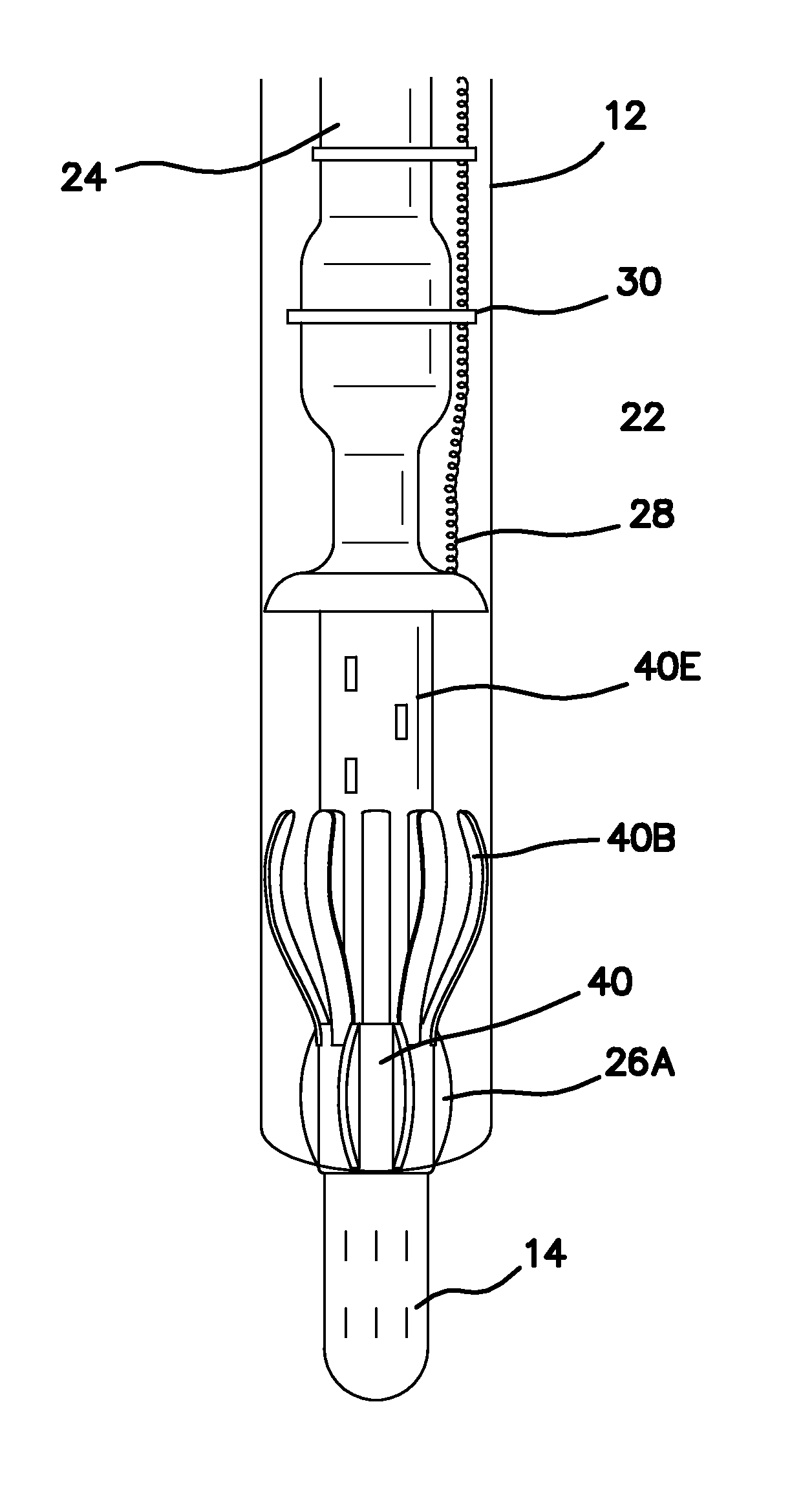
[0038]A band basket catcher 40 is placed above or below the submersible pump 22 to collect or scavenge broken bands as the production tubing 24 and pump 22 is withdrawn from the casing 12. The basket catcher 40 is made from a collar 40A used as a base that is modified to include a series of spring-tensioned blades 40B arranged radially and directed upwardly that, when dragged through the casing 12 catches and retains any broken bands 30 or other debris as the production tubing 24 and pump 22 are removed from the casing. The band basket catcher 40 thereby minimizes or eliminates the need for cleanout operations because it catches any broken bands as the pump is withdrawn.

[0039]The blades 40B together form a basket structure to catch broken bands 30 during pump withdrawal. Blades 40B are used in this embodiment but such a basket could conceivably be formed from structures other than the blades of the preferred embodiment and the scope of this disclosure is intended to also encompass t...


PUM


Abstract

A basket catcher for catching debris such as broken metal bands from an oil borehole casing as production tubing is withdrawn. The basket catcher has a collar that includes a series of spring-tensioned blades directed upwardly catch debris as the basket is withdrawn through the casing, preventing the debris from occluding the borehole.

Description

RELATED APPLICATIONS[0001]This application hereby claims the priority filing date of and incorporates by reference U.S. provisional patent application 61 / 313,425, filed Mar. 12, 2010, entitled Electric Submersible Pump Band Basket Catcher, inventors Gary Erickson and Ronald Dobson.COPYRIGHT NOTICE[0002]A portion of the disclosure of this patent document contains material which is subject to copyright protection. The copyright owner has no objection to the facsimile reproduction by anyone of the patent document or the patent disclosure as it appears in the Patent and Trademark Office patent file or records, but otherwise reserves all copyright rights whatsoever.FIELD OF THE INVENTION[0003]This invention relates to petroleum extraction and more particularly to a method and apparatus for clearing the borehole of an oil well bore.BACKGROUND OF THE INVENTION[0004]Referring now to the figures, in many environments crude oil is produced by boring a shaft or borehole 10 into the ground down...

Claims


Application Information

Patent Timeline
Patent Type & Authority Patents(United States)
IPC IPC(8): E21B31/08E21B17/02E21B27/00E21B43/12
CPCE21B17/026E21B43/128E21B27/00E21B31/08
Inventor DOBSON, RONALD E.ERICKSON, GARY J.
Owner BAND BASKETS LLC
Why Eureka
Try Eureka