Portable Refrigerant Recovery Machine

Active Publication Date: 2010-06-24
BOSCH AUTOMOTIVE SERVICE SOLUTIONS
View PDF19 Cites 17 Cited by
  • Summary
  • Abstract
  • Description
  • Claims
  • Application Information

AI Technical Summary

Problems solved by technology

A disadvantage to this arrangement is that the refrigerant will remove the lubrication in the moving components in the crankcase, which are typically ball bearings,

Method used


Image

  • Portable Refrigerant Recovery Machine
  • Portable Refrigerant Recovery Machine
  • Portable Refrigerant Recovery Machine

Examples


Embodiment Construction

[0016]The invention will now be described with reference to the drawing figures, in which like reference numerals refer to like parts throughout. An embodiment in accordance with the present invention provides a portable refrigerant recovery machine having opposed two cylinders in order to increase the work load of the machine.

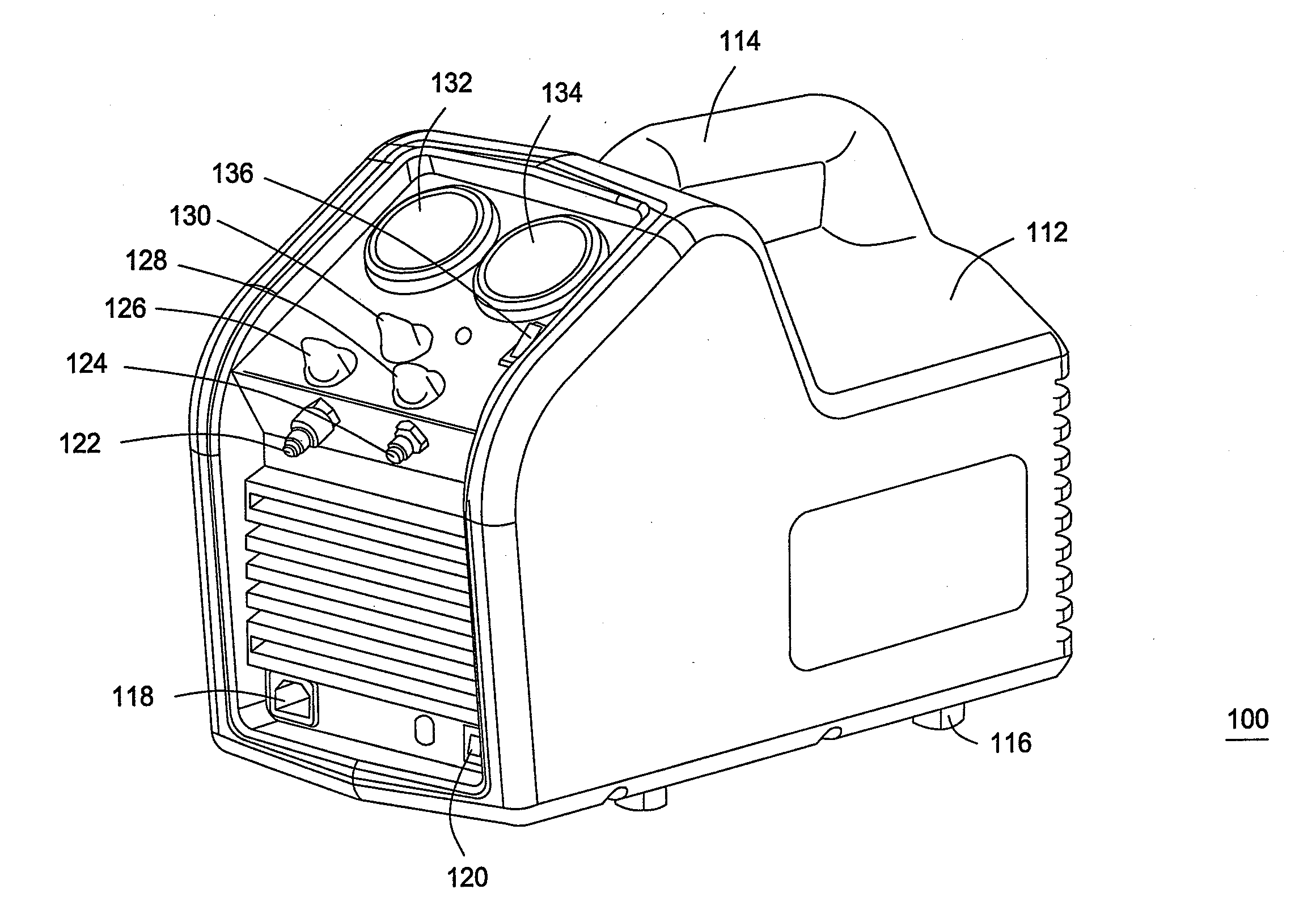
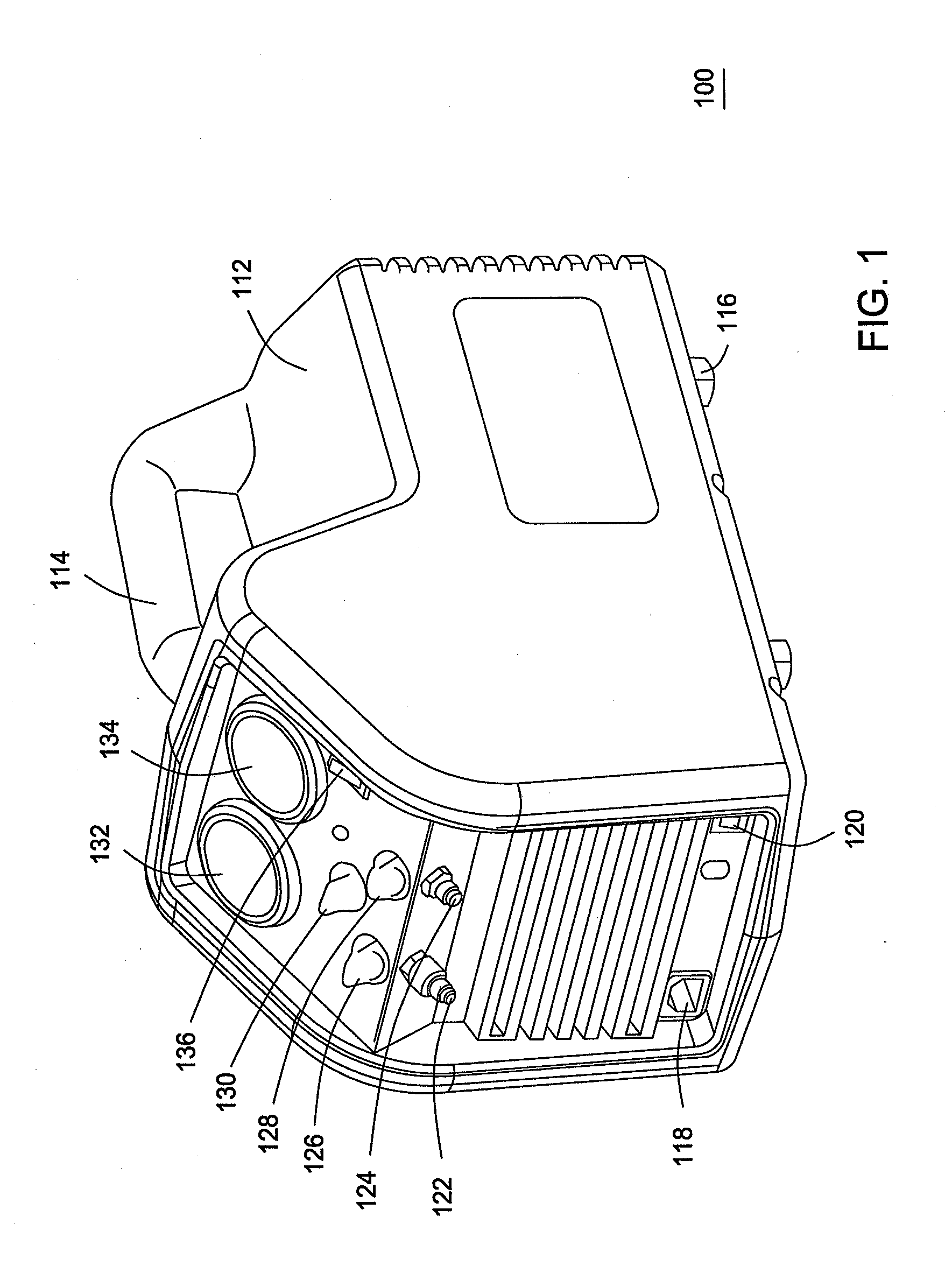
[0017]An embodiment of a portable refrigerant recovery machine 100 of the present invention is illustrated in FIG. 1. The recovery machine includes a case 112 that may be made from molded plastic and the like. The case 112 is designed to enclose the major components, discussed below, of the recovery machine 100. The recovery machine 100 also includes a handle 114 for a user to use to move the recovery machine from one place to another. The handle can be made from the same material as the case 112 or from an elastomeric material for more comfort to the user. Feet 116 are positioned on a bottom portion of the case 112 in order to keep the recovery machine 100 fr...


PUM


Abstract

A refrigerant recovery machine having two opposed and off-set pistons and its use are provided. The pistons are received in cylinders that are able to move depending on the alignment of the pistons. The two pistons in the compressor allow more volume of refrigerant than a single piston and because they are opposed and off-set allows for more even load on the motor.

Description

FIELD OF THE INVENTION[0001]The present invention relates generally a portable refrigerant recovery machine. More particularly, the present invention relates to a portable refrigerant recovery machine having opposed two-cylinder compressor for refrigerant transfer.BACKGROUND OF THE INVENTION[0002]Portable refrigerant recovery machines are used to transfer refrigerant from a refrigerant containing device, such as an air-conditioning unit for a home to a refrigerant storage tank. Many recovery machines are designed with a single cylinder, “oil less” compressor and include a pressurized crank case, which increases pressure during the intake stroke, thereby storing potential energy in the compressed refrigerant. As the piston begins the compression stroke, the stored potential energy in the compressor refrigerant in the crank case is used to help push the piston up the stroke and compress the refrigerant in the cylinder against the head pressure. This “assist” reduces the required load ...

Claims


Application Information

Patent Timeline
IPC IPC(8): F25B45/00F04B53/16F04B25/00
CPCF04B9/047F04B35/01F04B53/162F25B2345/005F25B2345/002F25B2345/0051F25B2345/006F25B45/00
Inventor SCHOENOFF, MICHAEL STEVENMCMASTERS, MARK
Owner BOSCH AUTOMOTIVE SERVICE SOLUTIONS
Why Eureka
Try Eureka