
Device for lifting at least one wheel of a railbound vehicle

a technology for railbound vehicles and lifting devices, which is applied in the direction of lifting devices, railway auxiliaries, manufacturing tools, etc., can solve the problems of rail-bound vehicles going off the rail, heavy equipment for lifting, and damage to rails

Inactive Publication Date: 2010-06-24
EUROMAINT AB
View PDF12 Cites 25 Cited by
  • Summary
  • Abstract
  • Description
  • Claims
  • Application Information

AI Technical Summary

Benefits of technology

[0004]The object of the present invention is to indicate a device allowing improved possibilities of repairing a damaged wheel of a rail-bound vehicle.
[0005]This object is achieved with a device according to the preamble of claim 1, which is characterized in that the force transfer element is shaped to receive a mainly horizontal force and to be displaced in a mainly horizontal direction, so that the oblique force transfer surface transfers a vertical lifting force to the wheel. By using an oblique force transfer surface a force change takes place, since the horizontal force may be smaller than the resulting vertical lifting force. Furthermore the driving device causing the horizontal force, for example a hydraulic cylinder, may be arranged horizontally, wherein there is more space available for the cylinder, since the length of the cylinder is not limited by the height of the rail-bound vehicle above the ground. The shape of the lifting device may thus be shaped so that the lifting device can be positioned horizontally close to the ground. This is further facilitated in that the lifting device is adapted to lift directly against the wheel and not against the wheel shaft or the gearbox. Furthermore the size and weight of the lifting device becomes substantially smaller, wherein the device more easily may be moved to the location of an immobile rail-bound vehicle. Hence the rail-bound vehicle may be repaired even though it is not inside a repair shop, which substantially decreases the downtime.
[0006]According to one embodiment the device comprises a rotation arrangement arranged to rotate the wheel around its wheel center, when the wheel is in an uplifted state. Preferably the rotation arrangement is arranged to rotate the wheel around a rotational axis coinciding with the wheel shaft of the wheel, or wheel-pair. Preferably the device also comprises a lathing arrangement adapted for turning the wheel profile of the wheel when the wheel is in the uplifted state. Thus the wheel may easily be turned in the lathe so that a damaged wheel obtains a new wheel profile so that the rail-bound vehicle may proceed to travel on the wheel. Hence the wheel or the wheel pair does not need to be changed.

Problems solved by technology

A damage on a wheel may cause damages on the rail or may cause the rail-bound vehicle to go off the rail.
Thus the equipment for lifting is very large and heavy so that such a hydraulic cylinder can only be provided in a repair shop.
This is a problem since wheel-bound vehicles are often damaged when the vehicle is far from a repair shop, wherein the vehicle can be left immobile.
These lifting cranes are relatively weak however, wherein for example a cargo wagon first needs to be emptied before the wagon can be lifted by the crane.
Thus the time for a stand still becomes very long.

Method used


Image

  • Device for lifting at least one wheel of a railbound vehicle
  • Device for lifting at least one wheel of a railbound vehicle
  • Device for lifting at least one wheel of a railbound vehicle

Examples


Embodiment Construction

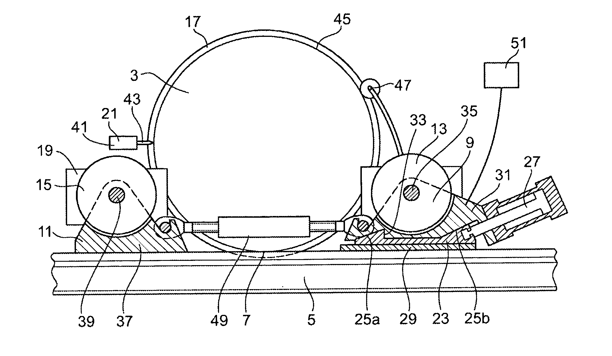
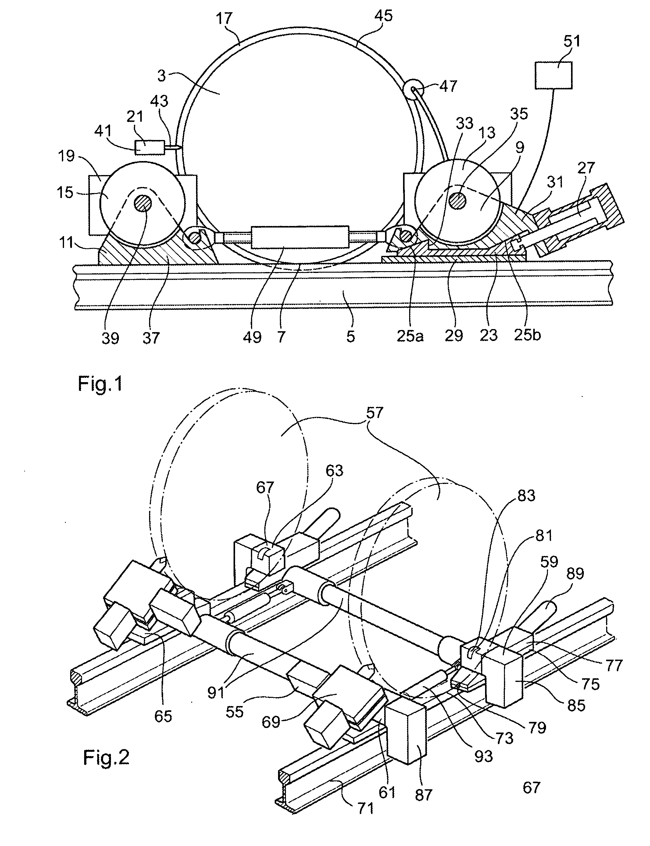
[0027]In FIG. 1 a device 1 according to a first embodiment of the invention is shown. In the figure a train wheel 3 resting on a rail 5 in a contact point 7 is also shown. The device 1 comprises a first lifting member 9 arranged on one side of the contact point 7, and a second lifting member 11 arranged on the other side of the contact point 7. The first and the second lifting members 9, 11 each comprises a lifting wheel 13, 15 arranged to bear on a flange 17 of the train wheel 3. The device 1 further comprises a rotation device 19 arranged to rotate the wheels 13, 15 in order to drive the rotation of the train wheel 3. The device 1 further comprises a lathing arrangement 21 arranged for turning the wheel profile of the train wheel 3 in the lathe.

[0028]The first lifting member 13 comprises a force transfer element 23. The force transfer element comprises two oblique force transfer surfaces 25a, 25b. The force transfer element 23 is further shaped to receive a mainly horizontal force...


PUM

PropertyMeasurementUnit
Forceaaaaaaaaaa
Distanceaaaaaaaaaa
Circumferenceaaaaaaaaaa

Abstract

The invention relates to a device for lifting at least one wheel (3, 57) of a rail-bound vehicle, which wheel bears on a rail (5, 71) in a contact point (7, 73). The device comprises a first (9, 59, 63) and a second lifting member (11, 61, 65) adapted to be positioned on each side of the contact point of the wheel, wherein at least the first lifting member comprises a force transfer element (23, 49) comprising an oblique force transfer surface (25a, 25b).

Description

TECHNICAL FIELD[0001]The present invention relates to a device for lifting at least one wheel of a rail-bound vehicle.PRIOR ART[0002]The wheels of rail-bound vehicles are provided with a special wheel profiles along their circumferences, in order to fit the rail. The circumference of the wheel comprises a treading bearing on the rail and a flange projecting our beside the rail in order to hold the rail-bound vehicle onto the rail. The wheels of the rail-bound vehicle are usually arranged in pairs, and the two wheels in one wheel-pair are rigidly connected with each other by a wheel-shaft. The two wheels of a wheel-pair thus usually rotates with the same rotation velocity.[0003]A damage on a wheel may cause damages on the rail or may cause the rail-bound vehicle to go off the rail. The vehicle must therefore be taken to the repair shop in which the vehicle is lifted, after which the wheel-pair with the damaged wheel is replaced. The wheels may thereafter be turned in a lathe so that ...

Claims


Application Information

Patent Timeline
IPC IPC(8): B23B5/28B66F3/00B66F11/00B61K9/12
CPCB23B5/32Y10T82/185Y10T82/2522B61K5/00B61K9/12
Inventor THYNI, KURT-GORAN
Owner EUROMAINT AB
Learn More