Humidifier tub for cpap device

a technology of humidifier tub and cpap device, which is applied in the direction of lighting and heating apparatus, combustion types, separation processes, etc., can solve problems such as water emerging, and achieve the effects of reducing pressure loss, reducing cost, and increasing moisture pickup

Active Publication Date: 2010-06-24
RESMED LTD
View PDF22 Cites 74 Cited by
  • Summary
  • Abstract
  • Description
  • Claims
  • Application Information

AI Technical Summary

Benefits of technology

[0009]One aspect of the invention relates to a low cost humidifier tub that allows increased ...

Problems solved by technology

Thus, over-filling will result in water emerging from the outle...

Method used


Image

  • Humidifier tub for cpap device
  • Humidifier tub for cpap device
  • Humidifier tub for cpap device

Examples


Embodiment Construction

1. Humidifier Tub

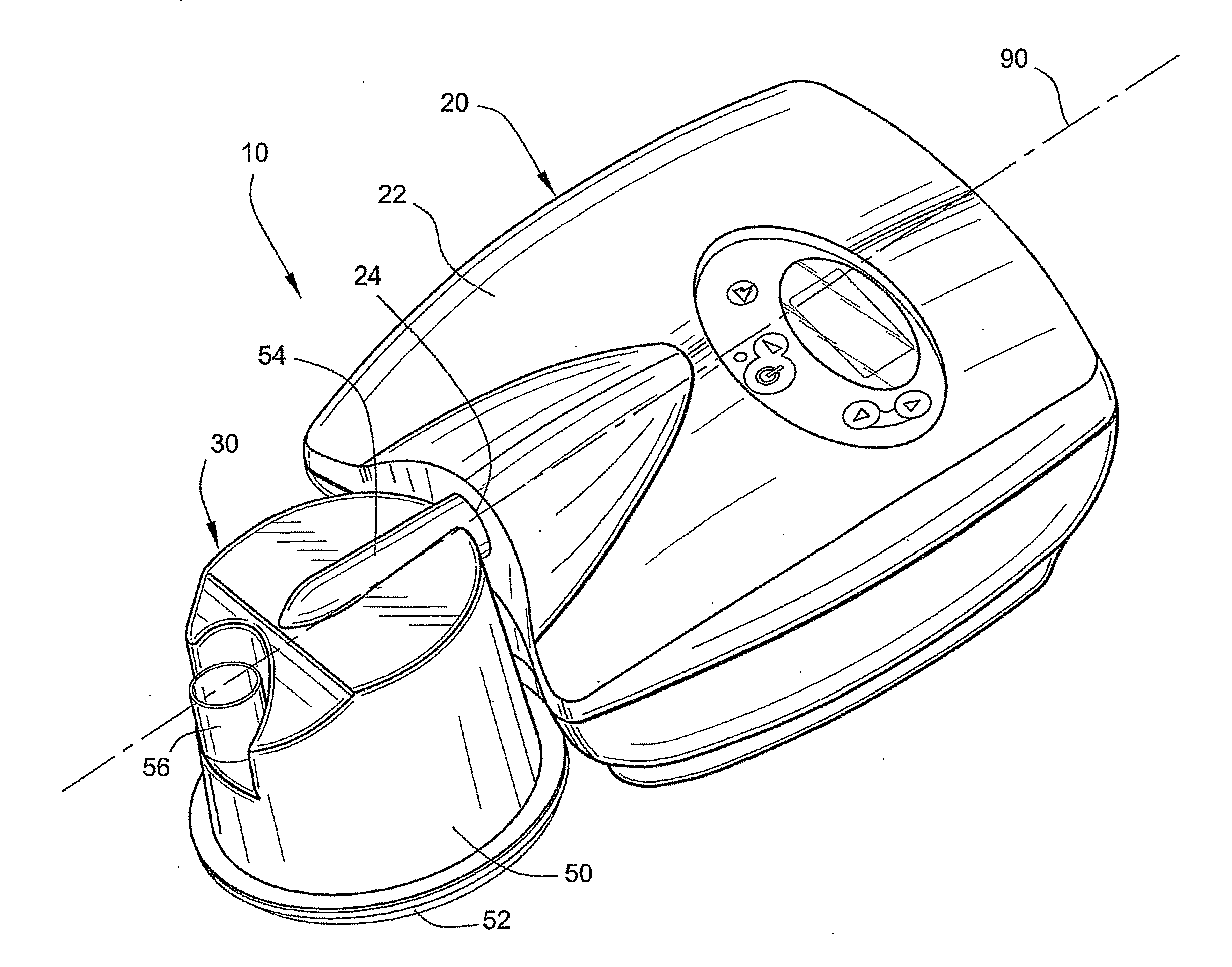
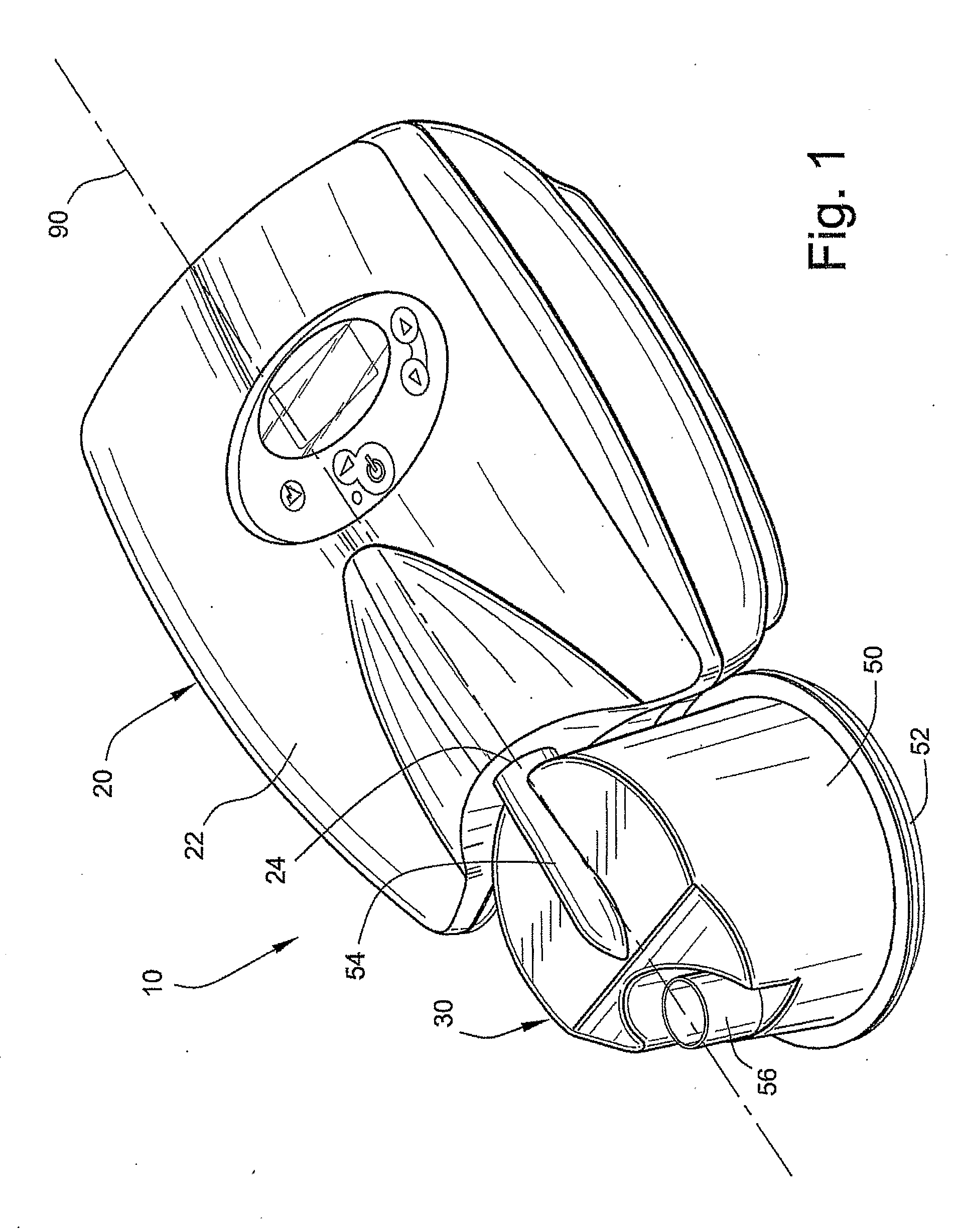
[0044]FIG. 1 illustrates a humidifier tub 50 for a humidifier 30 of a CPAP device 10 according to an embodiment of the present invention. As illustrated, the CPAP device 10 includes a flow generator 20 and a humidifier 30 provided to the flow generator 20.

[0045]The flow generator 20 includes a housing 22 and a blower (not shown) supported within the housing 22. As is known in the art, the blower is operable to draw a supply of air into the housing 22 through one or more intake openings and provide a pressurized flow of air at an outlet 24. In an embodiment, the flow generator 20 may be structured and controlled such as the flow generator described in U.S. Patent Application No. 60 / 707,951, entitled “Low Cost CPAP Flow Generator and Humidifier Assembly,” filed Aug. 15, 2005, the contents of which are incorporated in its entirety by reference herein.

[0046]The humidifier 30 includes the humidifier tub 50, which includes a base plate 52 sealed to the bottom of the tub 5...


PUM

PropertyMeasurementUnit
Lengthaaaaaaaaaa
Lengthaaaaaaaaaa
Thicknessaaaaaaaaaa

Abstract

A humidifier includes a humidifier tub including an air inlet and an air outlet. The air outlet may have an exit port positioned in a plane disposed below the air inlet. A base plate is provided to the bottom of the humidifier tub. The base plate and humidifier tub define a water chamber adapted to receive a volume of water. The humidifier tub may include a guidance structure adapted to direct air entering the humidifier tub via the air inlet to swirl downwardly and around within the humidifier tub reaching the water surface before exiting the exit port. The tub may include a structure to prevent the inadvertent entry of water from the tub to the flow generator.

Description

CROSS-REFERENCE TO PRIORITY APPLICATION[0001]This application claims the benefit of U.S. Provisional Application No. 60 / 707,949, filed Aug. 15, 2005, incorporated herein by reference in its entirety.FIELD OF THE INVENTION[0002]The present invention relates to an improved humidifier tub that is adapted to form part of a Continuous Positive Airway Pressure (CPAP) flow generator with a humidification system used to treat sleep disordered breathing (SDB) conditions such as Obstructive Sleep Apnea (OSA).BACKGROUND OF THE INVENTION[0003]Colin Sullivan was the first to invent the use of nasal Continuous Positive Airway Pressure (CPAP) to treat Obstructive Sleep Apnea (OSA), e.g., see U.S. Pat. No. 4,944,310. The treatment generally provides a supply of air or breathable gas from a blower to a patient via an air delivery conduit and a patient interface, such as a full-face or nasal mask or nasal prongs. The air or breathable gas is commonly delivered at a pressure of 4 cm H20 to 20 cm H20 a...

Claims


Application Information

Patent Timeline
IPC IPC(8): A61M16/10B01F3/04B05B9/03
CPCA61M16/16A61M16/109A61M2206/16A61M16/0066A61M16/0666A61M16/0875A61M2206/14
Inventor SMITH, IAN MALCOLMBONILLA, WILLIAMJONES, RICHARD LLEWELYN
Owner RESMED LTD
Why Eureka
Try Eureka