
Tire tread with groove reinforcement

a technology of tire tread and reinforcement, applied in the field of tires, can solve the problems of ply turnup ends being prone to separation from adjacent structural elements of tires, and the separation of mutually adjacent components

Inactive Publication Date: 2010-06-24
THE GOODYEAR TIRE & RUBBER CO
View PDF38 Cites 71 Cited by
  • Summary
  • Abstract
  • Description
  • Claims
  • Application Information

AI Technical Summary

Benefits of technology

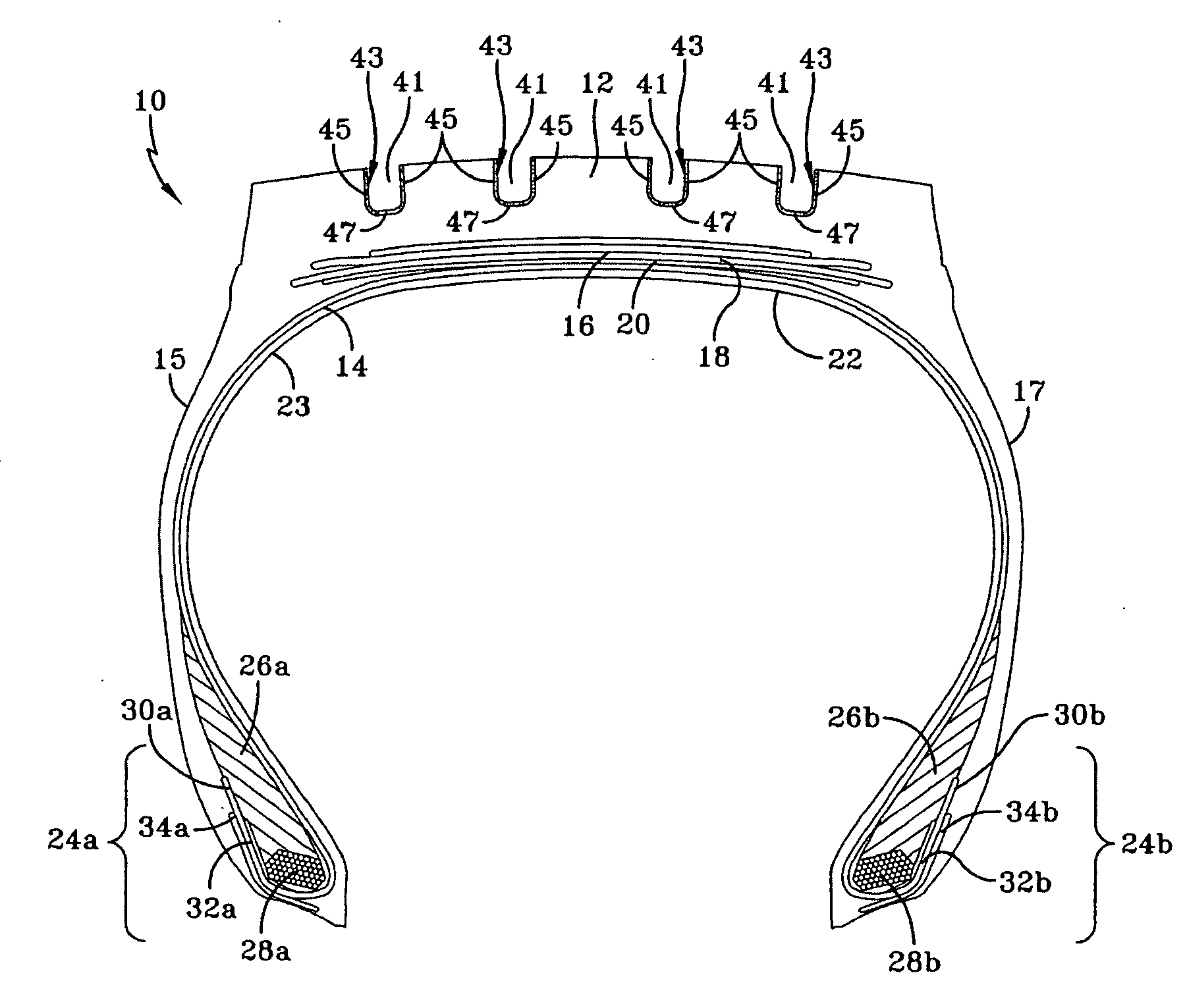
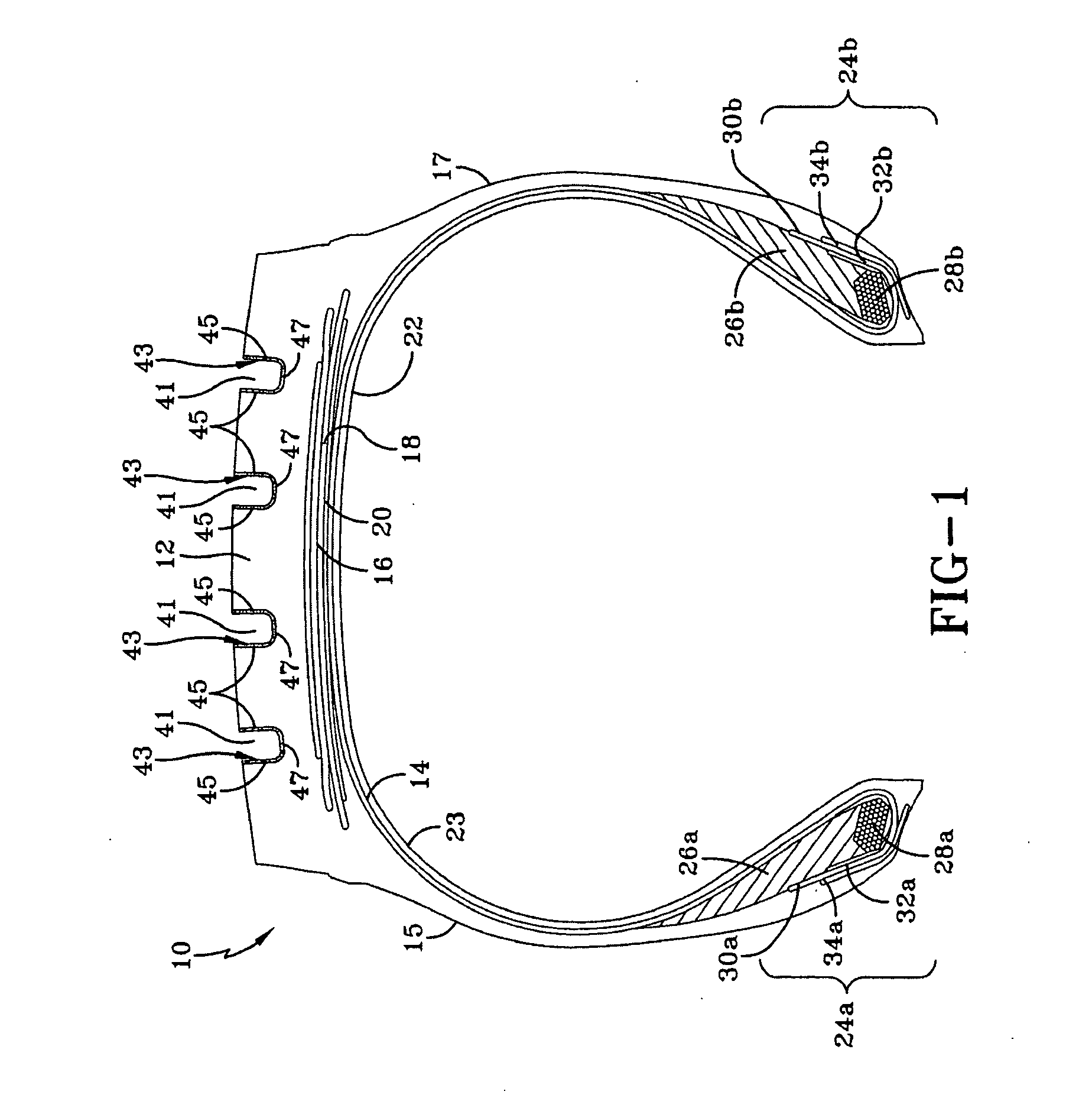
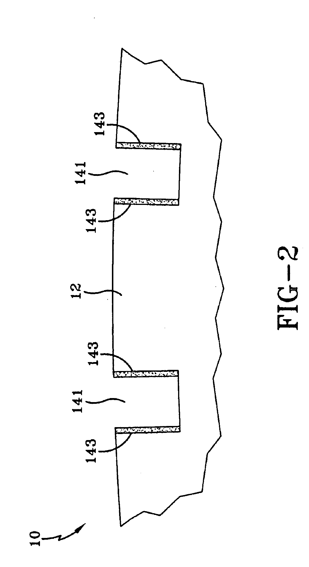
[0005]A tire in accordance with the present in invention has an axis of rotation. The tire includes two sidewalls extending radially outward and a tread disposed radially outward of the two sidewalls and interconnecting the two sidewalls. The tread includes a main portion comprising a first compound and a reinforcing structure comprising a second compound having reinforcing short fib

Problems solved by technology

The bead area is one part of the tire that contributes a substantial amount to the rolling resistance of the tire, due to cyclical flexure which also leads to heat buildup.
Under conditions of severe operation, as with runflat and high performance tires, the flexure and heating in the bead region can be especially problematic, leading to separation of mutually adjacent components that have disparate properties, such as the respective moduli of elasticity.
In particular, the ply turnup ends may be prone to separation from adjacent structural elements of the tire.

Method used


Image

  • Tire tread with groove reinforcement
  • Tire tread with groove reinforcement
  • Tire tread with groove reinforcement

Examples


example 1

[0088]In this example, the effect of adding a short fiber to the second compound for the reinforcing structures 43 or 143 according to the present invention is illustrated. Rubber compositions containing diene based elastomer, fillers, process aids, antidegradants, and curatives were prepared following recipes as shown in Table 1, with all amounts given in parts by weight per 100 parts by weight of base elastomer (phr). Sample 1 contained no short fiber and served as a control. Sample 2 included Sulfron® 3000 short fibers mixed as a masterbatch of the short fibers in natural rubber.

[0089]Rubber samples were milled into a sheet and cut into tensile test specimens. Tensile test specimens were cut in two orientations, one with the test pulling direction parallel with the milling direction of the specimen, and one with the test pulling direction perpendicular with the milling direction of the specimen. In this way, the effect of fiber orientation (generally in the direction of milling) ...

example 2

[0091]In this example, the effect of adding a short fiber to the second compound for the reinforcing structures 43 or 143 according to the present invention is illustrated. Rubber compositions containing diene based elastomer, fillers, process aids, antidegradants, and curatives were prepared following recipes, as shown in Table 1, with all amounts given in parts by weight per 100 parts by weight of base elastomer (phr). Sample 3 contained no short fiber and served as a control. Sample 4 included Sulfron® 3000 short fiber mixed as a masterbatch of the short fibers in natural rubber.

[0092]Sample 5 included a chopped short aramid fiber treated with nylon. As in Sample 2 and Sample 4, Sample 5 may be formed by mixing a chopped or a chopped and fibrillated short fiber masterbatch into the remaining natural rubber compound.

[0093]Rubber samples were milled into a sheet and cut into tensile test specimens. Tensile test specimens were cut in two orientations, one with the test pulling direc...


PUM


Abstract

A tire has an axis of rotation. The tire includes two sidewalls extending radially outward and a tread disposed radially outward of the two sidewalls and interconnecting the two sidewalls. The tread includes a main portion comprising a first compound and a reinforcing structure comprising a second compound having reinforcing short fibers oriented between −20 degrees to +20 degrees to a circumferential direction of the tread. The main portion of the tread includes at least one circumferential groove separating circumferential ribs. Each circumferential groove has two sides and a base therebetween. The reinforcing structure includes a layer of the second compound secured to the sides of each circumferential groove.

Description

FIELD OF THE INVENTION [0001]The present invention relates to a tire, and more particularly, to a tire tread with groove reinforcement.BACKGROUND OF THE INVENTION [0002]A pneumatic tire typically includes a pair of axially separated inextensible beads. A circumferentially disposed bead filler apex extends radially outward from each respective bead. At least one carcass ply extends between the two beads. The carcass ply has axially opposite end portions, each of which is turned up around a respective bead and secured thereto. Tread rubber and sidewall rubber are located axially and radially outward, respectively, of the carcass ply.[0003]The bead area is one part of the tire that contributes a substantial amount to the rolling resistance of the tire, due to cyclical flexure which also leads to heat buildup. Under conditions of severe operation, as with runflat and high performance tires, the flexure and heating in the bead region can be especially problematic, leading to separation o...

Claims


Application Information

Patent Timeline
IPC IPC(8): B60C11/00
CPCB60C11/00B60C11/1346B60C2200/06B60C11/14
Inventor DAHLBERG, JOHAN PETERGEELEN, STEPHANE JOSELECHTENBOEHMER, ANNETTECORVASCE, FILOMENO GENNAROPINGENAT, MATTHIEUBROCHET, PIERRE BERNARD RAOULPERONNET-PAQUIN, ANNE THERESEWOJCIK, JACEKDHEUR, JEAN LUCLAMBERT, ISABELLE LEA LOUISE MARIE
Owner THE GOODYEAR TIRE & RUBBER CO
Learn More