Pneumatic tire

a technology of pneumatic tires and spherical tubes, which is applied in the direction of vehicle components, transportation and packaging, non-skid devices, etc., can solve the problems of difficult to obtain a sufficient water sucking effect by sipes, and difficulty in ensuring a sufficient path for water to be let out, so as to achieve a raised braking performance on ice

Active Publication Date: 2010-06-24
BRIDGESTONE CORP
View PDF5 Cites 16 Cited by
  • Summary
  • Abstract
  • Description
  • Claims
  • Application Information

AI Technical Summary

Benefits of technology

[0037]According to the present invention, by further increasing the amount of water that can be sucked up within sipes, a pneumatic tire can be made with raised braking performance on ice.

Problems solved by technology

However, since previously the amount of water that can be sucked up by the sipes was not large, it was difficult to secure a sufficient path for water to be let out, particularly at temperatures where water is readily generated on an icy surface.
Therefore, there have been cases where a state arises in which the tread rides on a film of water, and it has been difficult to obtain a sufficient water sucking up effect by sipes.

Method used


Image

  • Pneumatic tire
  • Pneumatic tire
  • Pneumatic tire

Examples


first exemplary embodiment

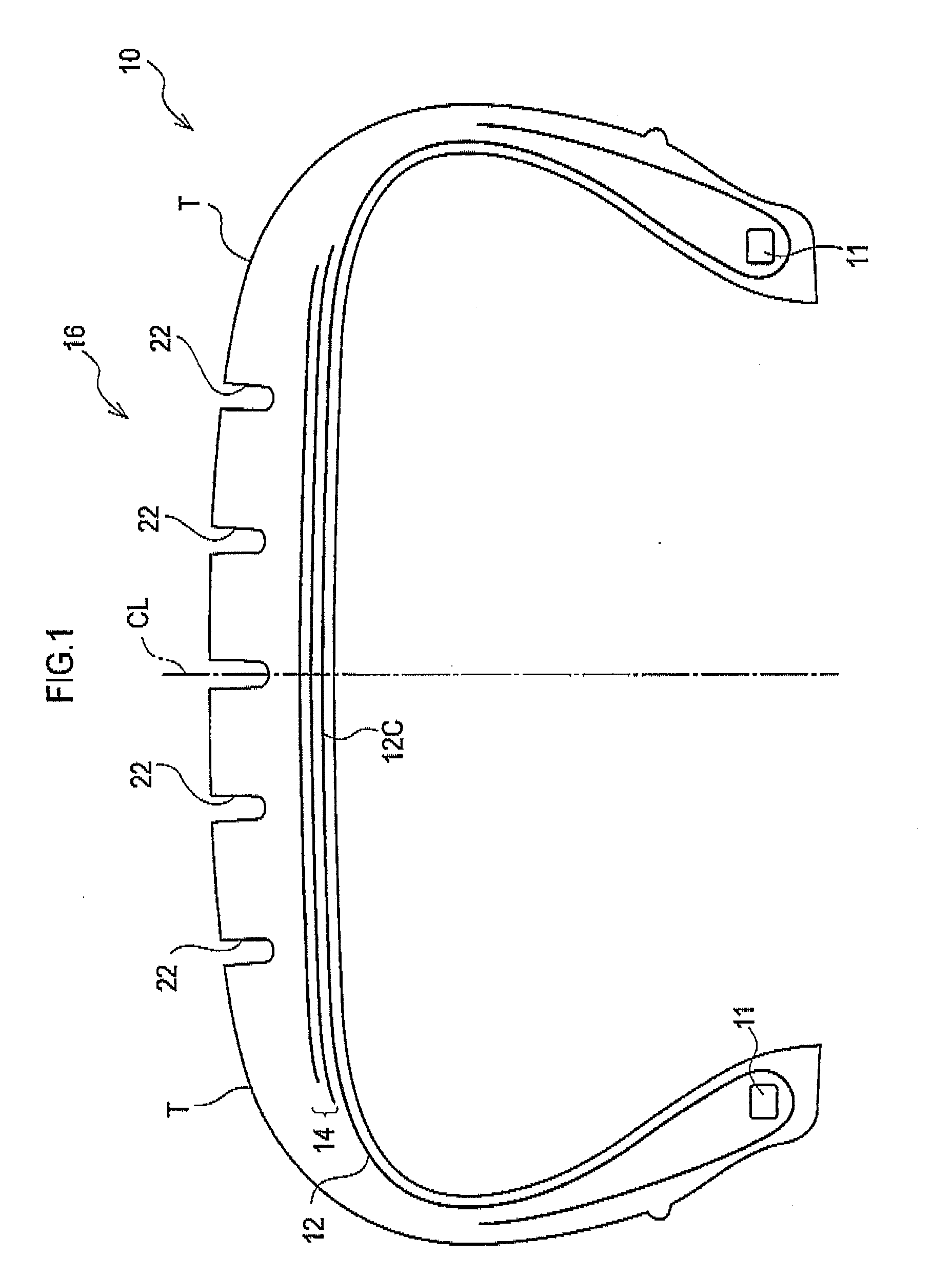
[0066]Explanation will first be given of a first exemplary embodiment. As shown in FIG. 1, a pneumatic tire 10 according to the present exemplary embodiment is equipped with a carcass 12 configured from a single layer, or from plural layers, wrapped around bead cores 11 at each edge thereof.

[0067]A belt layer 14 is buried within the tire at the tire radial direction outside of a crown portion 12C of the carcass 12, the belt layer 14 being configured with plural overlapping sheets (for example two sheets) of belt ply.

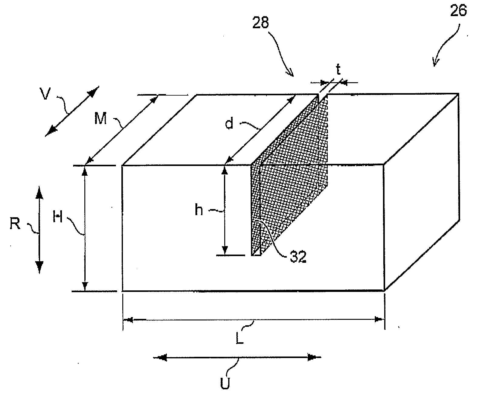
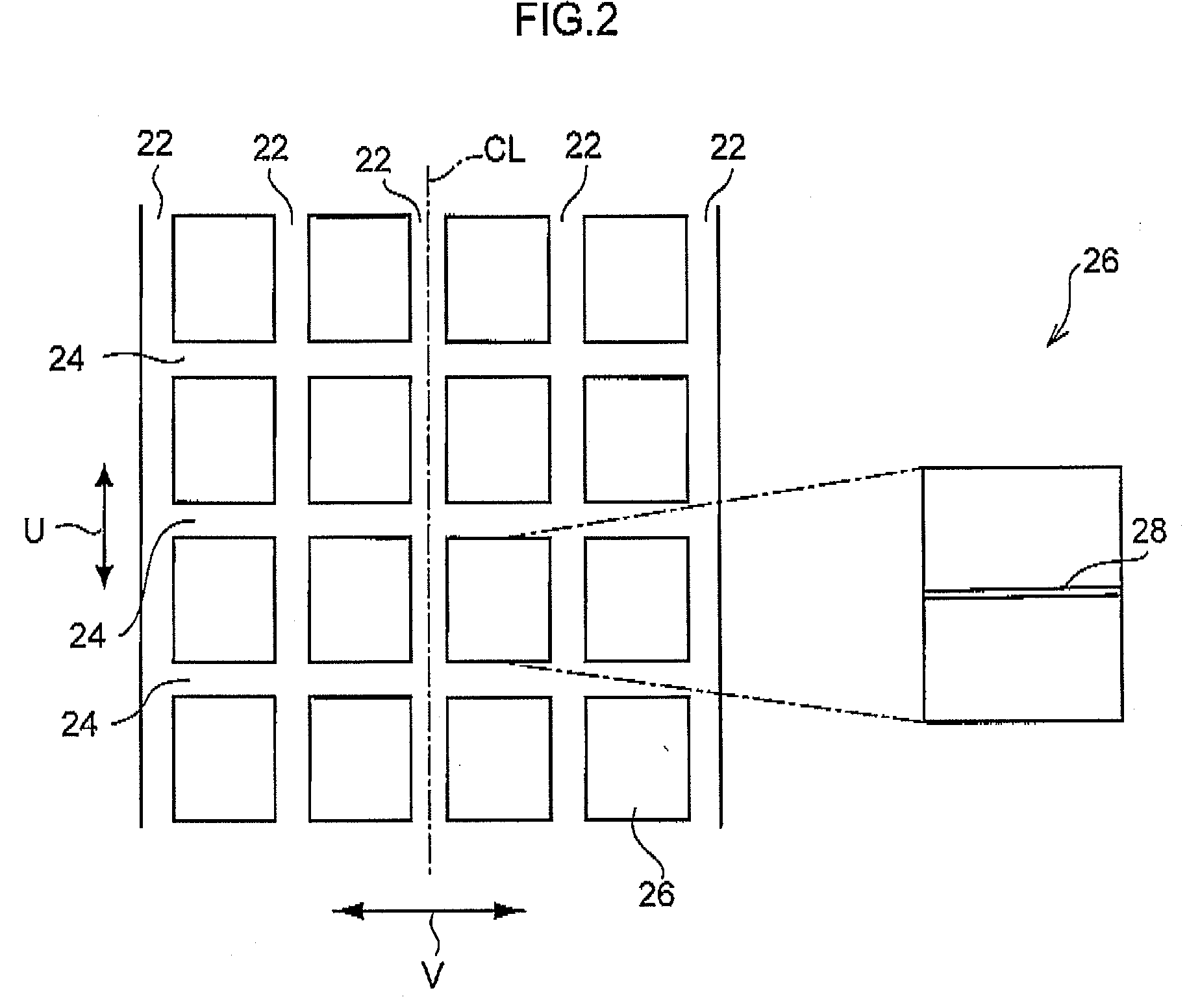
[0068]A tread 16 is formed at the radial direction of the tire outside of the belt layer 14, and grooves are disposed in the tread 16. The tread 16, as shown in FIG. 2, has plural circumferential direction grooves (main grooves) 22 formed so as to run along the tire circumferential direction U on the plane of the tire equator CL, and on both sides thereof. Plural transverse grooves 24 are also formed in the tread 16 intersecting with the tire circumferential direction U....

second exemplary embodiment

[0103]Explanation will now be given of a second exemplary embodiment. As shown in FIG. 15, a pneumatic tire 110 according to the present exemplary embodiment is equipped with a carcass 112 configured from a single layer, or from plural layers, wrapped around bead cores 111 at each edge thereof.

[0104]A belt layer 114 is buried within the tire at the tire radial direction outside of a crown portion 1120 of the carcass 112, the belt layer 114 being configured with plural overlapping sheets (for example two sheets) of belt ply.

[0105]A tread 116 is formed at the tire radial direction outside of the belt layer 114, and grooves are disposed in the tread 116. The tread 116, as shown in FIG. 16, has plural circumferential direction grooves (main grooves) 122 formed so as to run along the tire circumferential direction U on the plane of the tire equator CL, and on both sides thereof. Plural transverse grooves 124 are also formed in the tread 116 intersecting with the tire circumferential dire...

third exemplary embodiment

[0124]Explanation will now be given of a third exemplary embodiment. FIG. 22 is a diagram showing a tread of a pneumatic tire 151 in the present exemplary embodiment.

[0125]Circumferential direction grooves 152, transverse grooves 153, and blocks 154 are formed to the tread of the pneumatic tire 151.

[0126]The circumferential direction grooves 152 are grooves that extend along the tire circumferential direction (the direction of arrow U). The transverse grooves (width direction grooves) 153 are grooves that extend along the tire width direction (the direction of arrow V). The blocks 154 are blocks partitioned by the intersection of the circumferential direction grooves 152 and the transverse grooves 153, and are blocks having sipes 155. The blocks 154 are configured with central region blocks 154a and edge region blocks 154b.

[0127]The central region blocks 154a are blocks formed at a central region A of the tread. The edge region blocks 154b are blocks formed at edge regions B of the...


PUM


Abstract

A pneumatic tire having enhanced on-ice braking performance achieved by further increasing the amount of water that can be sucked up into sipes. In the pneumatic tire, blocks (26) partitioned by circumferential grooves and lateral grooves are formed in the tread. A sipe (28) is formed in a block (26), and a fine structure (32) having a height in the range of from 1 / 50 of the sipe width t to less than 1 / 10 of the sipe width t is formed on a sipe wall surface. This reduces fluid friction coefficient of water relative to the sipe wall surface to a lower level than conventional products. As a result, when water staying on ice comes into contact with the sipe wall surface, the water is more easily sucked up into the sipe. The construction increases the amount of water that can be sucked up into the sipe (28) or the removal amount of water that stays on ice etc., and this enhances braking performance (friction characteristics) on ice.

Description

TECHNICAL FIELD [0001]The present invention relates to a pneumatic tire with plural blocks having sipes formed in a tread.RELATED ART [0002]The letting out of water generated on ice through sipes formed in treads of tires has previously been performed in order to raise the braking performance on ice. However, since previously the amount of water that can be sucked up by the sipes was not large, it was difficult to secure a sufficient path for water to be let out, particularly at temperatures where water is readily generated on an icy surface. Therefore, there have been cases where a state arises in which the tread rides on a film of water, and it has been difficult to obtain a sufficient water sucking up effect by sipes.[0003]Sipe structures disclosed in Patent Publications 1 and 2 have been considered as a counter measures to the above. Also, a so-called tusked sipe is disclosed in Patent Publication 3, with projections formed to the sipe internal walls, preventing the sipe from ad...

Claims


Application Information

Patent Timeline
Patent Type & Authority Applications(United States)
IPC IPC(8): B60C11/12
CPCB60C11/1218B60C11/12B60C11/1263
Inventor KAJI, YOSHIOWATABE, RYOICHISAEKI, KENTAROKUROKAWA, MAKATO
Owner BRIDGESTONE CORP
Why Eureka
Try Eureka