Watering system for plants

a plant and watering system technology, applied in the field of plant watering system, can solve the problems of not being able to precisely control the amount of water that is absorbed by the soil and the plant, the difference between conventional methods and the requirements of differences, and taking a lot of time and labor power, so as to reduce the amount of water reaching the soil outside the tank, increase and increase the distance between the water level of the planting hol

Inactive Publication Date: 2016-06-23
LI YI HSI
View PDF11 Cites 9 Cited by
  • Summary
  • Abstract
  • Description
  • Claims
  • Application Information

AI Technical Summary

Benefits of technology

[0018]The advantages of the present invention is that the planting hole of the present invention is filled with soil, and the water level control unit is connected with a hose. By the float member of the water level control unit and the inlet valve, the water level in the tank and the water level in the tubular member is substantially at the same height. The movement of the float member of the water level control unit controls the water level of the tank so as to adjust the distance between the water level in the planting hole and the open top of the tank. Therefore, when the float member of the water level control unit moves lower, the distance between the water level in the planting hole and the open top of the tank is increased, the water is difficult to reach the open top of the tank due to gravity and the permeating force of the water, such that the amount of water reaching the soil outside of the tank is reduced. On the contrary, when the float member of the water level control unit moves higher, the water level of the planting hole increases and the distance between the water level in the planting hole and the open top of the tank is shortened, the water is easily to reach outside of the tank and the amount of water reaching the soil outside of the tank is increased. When the float member moves upward to drive the seal to seal the inlet vale when the water level of the water level control unit reaches a pre-set height. When the float member moves downward to remove the seal from the inlet vale when the water level of the water level control unit is lowered to a pre-set height.
[0019]The present invention also provides a bottle unit which is used to water the plants in one to three pots to save expenses. The water bottle unit is connected to the observation member and the tube is inserted into the planting hole. When the water level in the planting hole is higher than the lower open end of the tube, the pressure in the bottle unit is balanced with the atmosphere so that the water bottle unit stops to supply water. On the contrary, when the water level in the planting hole is lower than the lower open end of the tube, there is a difference between the pressure in the bottle unit and the atmosphere so that the water bottle unit starts to supply water so as to automatically maintain the water level of the planting hole.
[0020]The present invention does not need electricity to supply water to the soil outside the planting hole, such that the plants are supplied with suitable amount of water. The plants can be watered automatically to save the use of water and the owner's time. The plants are not drawn or dried out because of improper way of water supply. The outlet is located within the soil so that the water is not lost easily. The roots of the plants are convenient to absorb water and the owner easily manages the watering of the plants.
[0021]The present invention is suitable for watering the plants in one pot. The pots can also be connected to each other by using connection pipes and the tanks, such that the present invention is able to water the plants in a larger area such that the expenses, the time and the cost of labor can be saved.
[0022]The present invention uses the transparent pipe or the observation member and the float member to easily observe the water level of the tubular member and the tank. Because the water level in the tank affects the level of permeation of water in the soil so that when the water level is too high or too low relative to the plants or the level of permeation in the soil, the securing member is adjusted to adjust the position of the outlet end in the guide tube such that the height of the float member in the water control unit is adjusted. By the adjustment of the threaded section of the rod relative to the locking hole, the height of the float member can be micro-adjusted to precisely set the water level of the tank. Accordingly, the water level of the tank is able to control the amount of water entering into the soil to provide the suitable amount water to the plants. Furthermore, by adjusting the water level control unit and the height of the float member, not only the water level of the tank can be controlled, the present invention can also be used on different terrains or different types of water supply devices.
[0023]When the water pressure from the water supply is too high, the pressure reduction unit is used to regulate the water pressure to prevent failure of the seal of the inlet valve.

Problems solved by technology

However, both of these methods cannot precisely control the amount of water that is absorbed by the soil and the plants.
Different plants need different amount of water, so that the conventional ways cannot meet the requirements of the differences.
Besides, when watering a huge planting area, it takes a lot of time and labor power.
Furthermore, the sprinklers require significant expenses and is not suitable for the plants in a smaller area.
For the plants in pots, exceed water flows over the pot easily contaminates the floor and may attract mosquitoes.

Method used


Image

  • Watering system for plants
  • Watering system for plants
  • Watering system for plants

Examples


Embodiment Construction

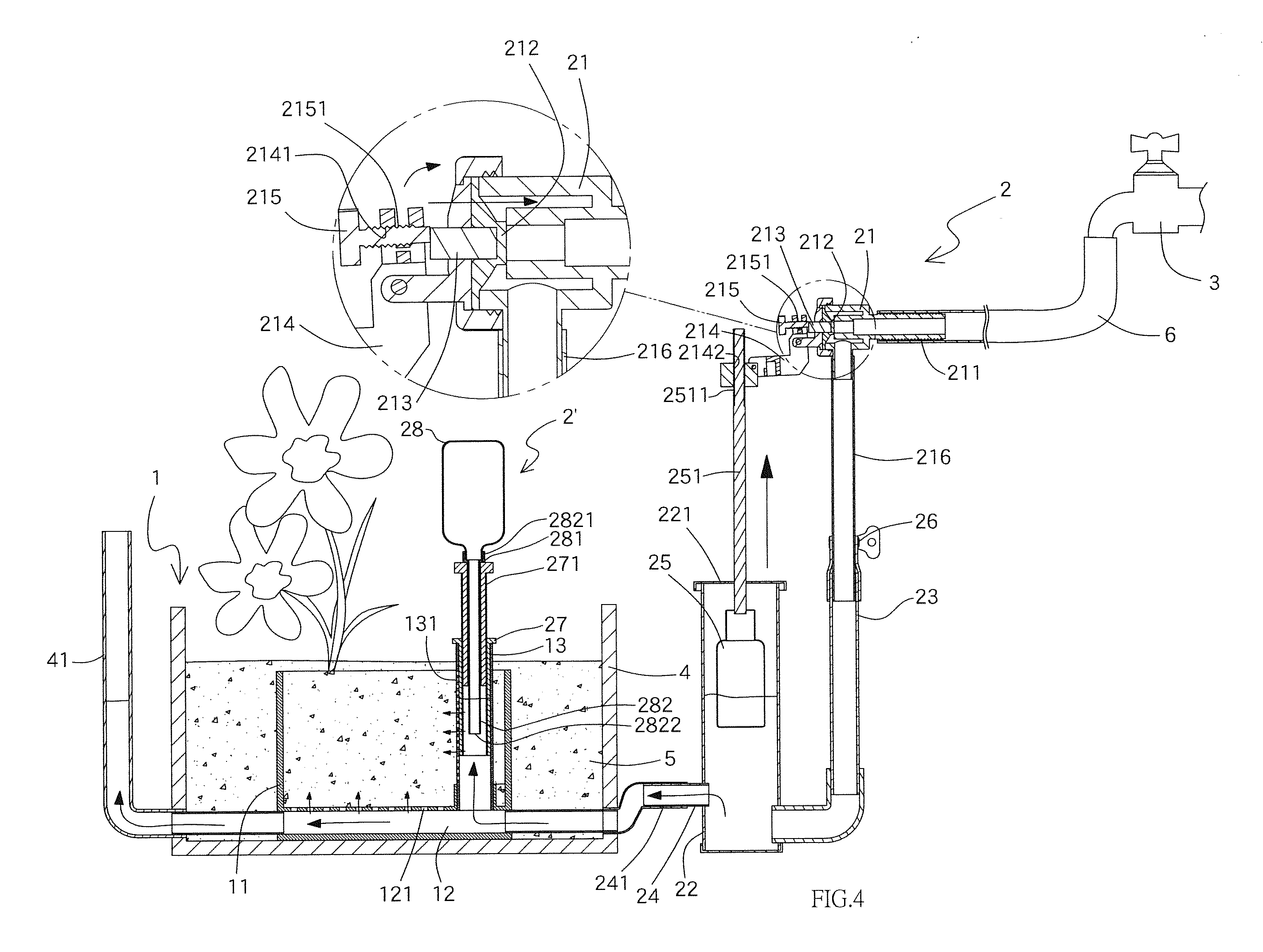
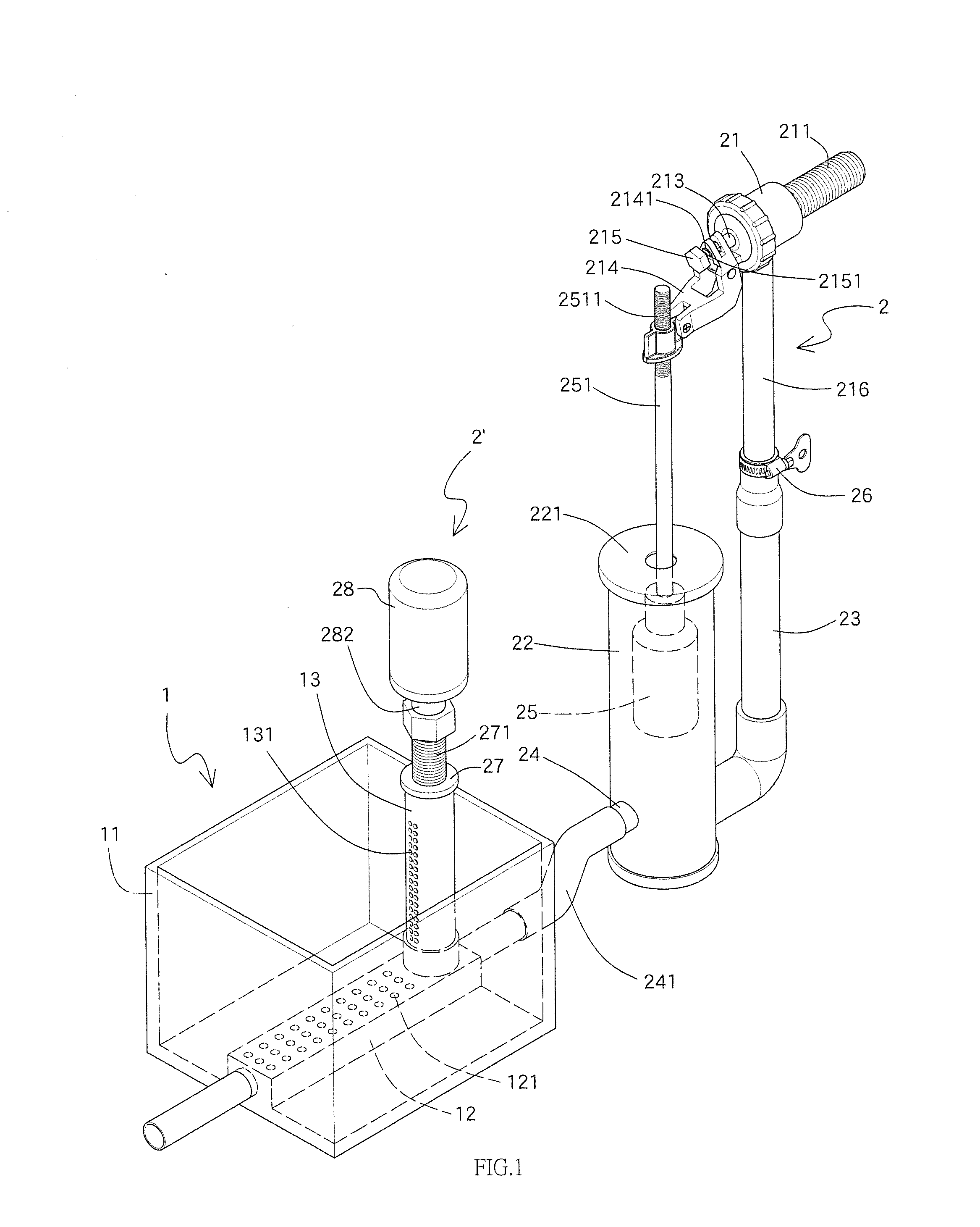
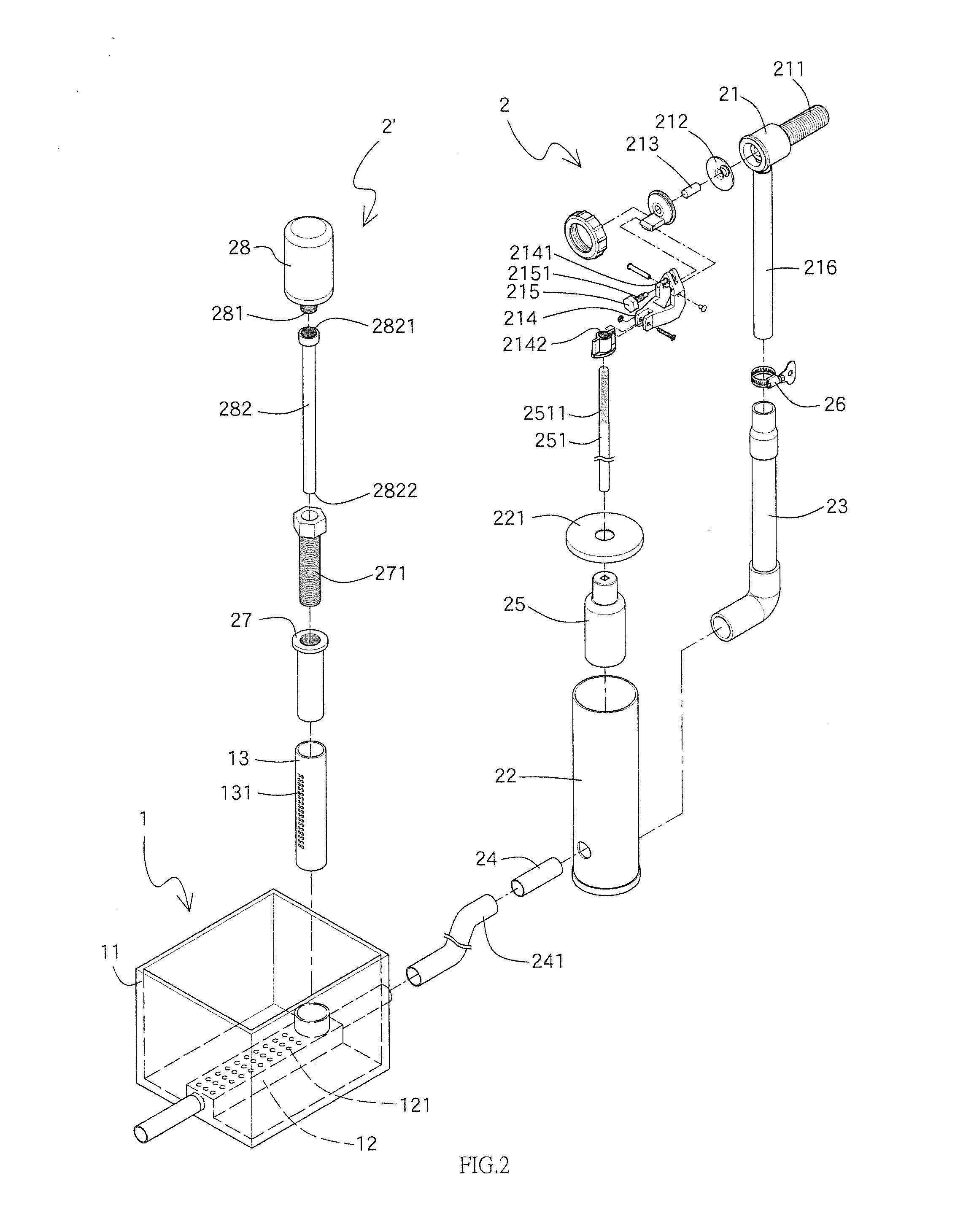
[0036]Referring to FIGS. 1 and 2, the watering system of the present invention comprises a planting hole 1, a water level control unit 2 or a bottle unit 2′. The planting hole 1 has a tank 11 (water cannot permeate through the tank) located therein and a water pipe 12 is located at the inner end of the planting hole 1 and communicates with the bottom of the tank 11. An observation member 13 is perpendicularly connected to and communicated with the water pipe 12. The water pipe 12 has at least one hole 121 which communicates with the tank 11. The observation member 13 has multiple slots 131 defied through the wall thereof and the slots 131 are located lower than the top of the tank 11. The observation member 13 has a float tube 14 or the bottle unit 2′. The bottle unit 2′ has a bottle 28, a tube 282 and a height adjuster 27. When the observation member 13 is not cooperated with the float tube 14, a dust cap 132 is mounted to the open top of the observation member 13 as shown in FIG. ...


PUM


Abstract

A watering system includes a bottle unit or a water level control unit which has a float member to control the water level of the tank in a planting hole. The float member controls the operation of the water inlet valve and the water level in the bottle unit so as to control the amount of water that the planting hole provides to the soil outside the planting hole without using electricity. The plants are properly watered automatically all day long. The water permeates into the soil outside the planting hole to water the plants that are planted in a larger area. The watering system is suitable for watering the plants in a large area or in pots.

Description

BACKGROUND OF THE INVENTION[0001]1. Fields of the Invention[0002]The present invention relates to a watering system, and more particularly, to a watering system for providing water to plants without use of electricity.[0003]2. Descriptions of Related Art[0004]The conventional way for watering plants is to use a bottle in which water is received, and manually pour the water from the bottle. A more advanced method is to install sprinklers which are cooperated with a water supply system to water the plants according pre-set time schedule. However, both of these methods cannot precisely control the amount of water that is absorbed by the soil and the plants. Different plants need different amount of water, so that the conventional ways cannot meet the requirements of the differences. Besides, when watering a huge planting area, it takes a lot of time and labor power. Furthermore, the sprinklers require significant expenses and is not suitable for the plants in a smaller area. For the pl...

Claims


Application Information

Patent Timeline
Patent Type & Authority Applications(United States)
IPC IPC(8): A01G27/00
CPCA01G27/003A01G27/008A01G27/005
Inventor LI, YI-HSI
Owner LI YI HSI
Why Eureka
Try Eureka