

Sediment and sludge dewatering by vacuum bag method
- Summary
- Abstract
- Description
- Claims
- Application Information
AI Technical Summary
Benefits of technology
Problems solved by technology
Method used
Image

Examples
second embodiment
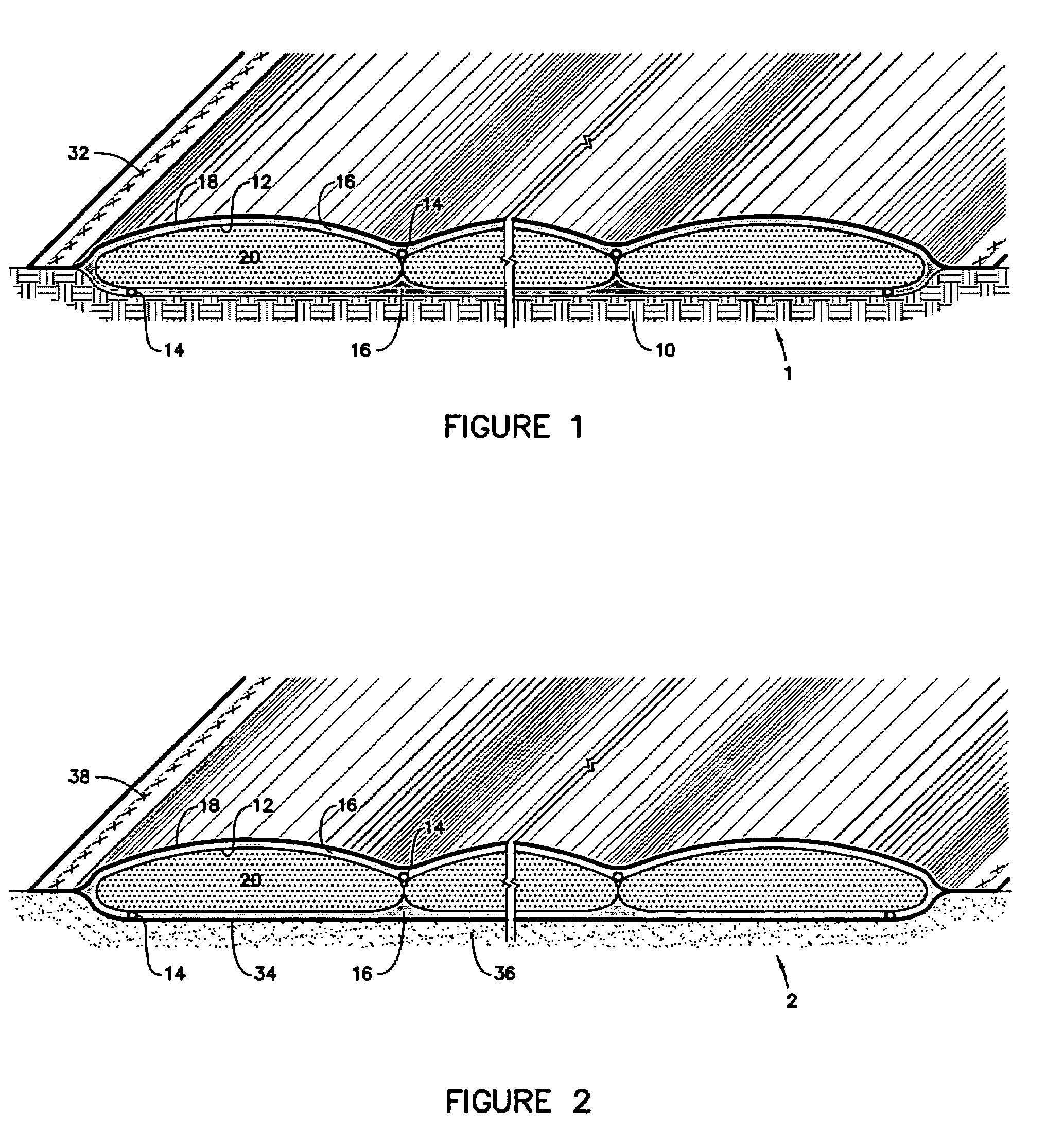
[0046]FIG. 2 discloses the vacuum bag method 2. A second air impermeable sheet 34 is used if the foundation 36 is permeable. The perimeter of the impermeable sheet 18 is sealed 38 to a perimeter of the second impermeable sheet 34, with the at least one sediment enclosure 12, any drain tubes 14, porous media spacer 16, and the dredged sediment or sludge 20 contained therein.
third embodiment
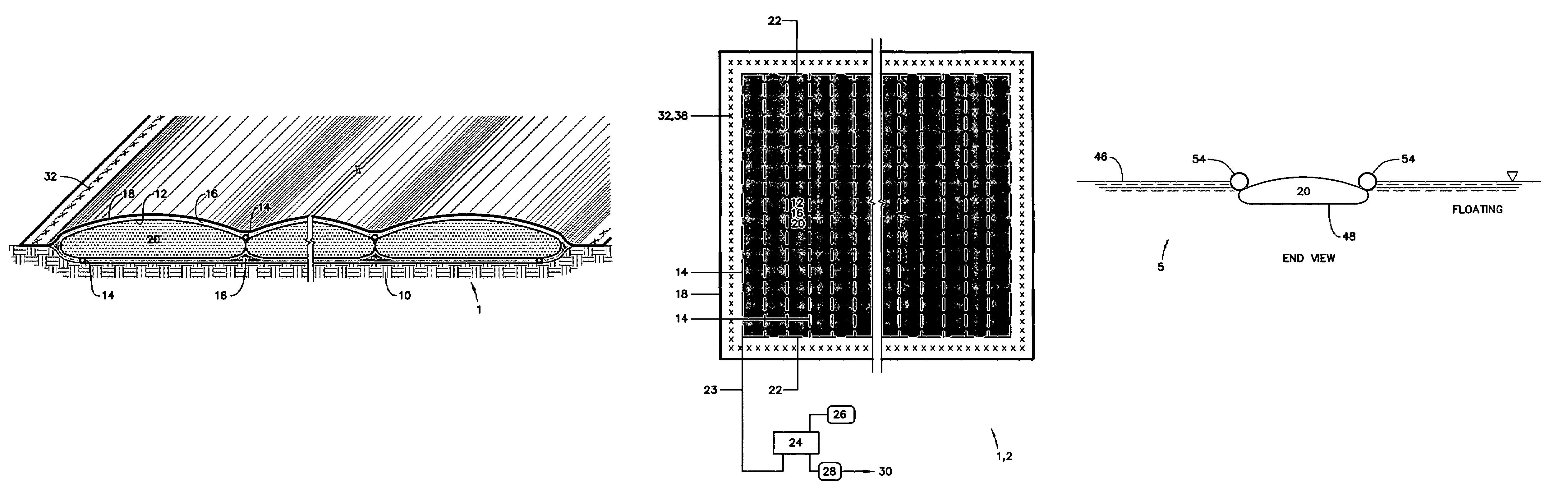
[0047]FIG. 4 discloses the vacuum bag method 3. The at least one sediment or sludge enclosure 12 is placed in a barge 40. The air impermeable sheet 18 is sealed 42 to side walls 44 of the barge 40. The barge 40 floats in a body of water 46.
fourth embodiment
[0048]FIG. 5 discloses the vacuum bag method 4, in the form of a composite vacuum bag 48. The composite vacuum bag 48 includes the sediment or sludge enclosure 12, any drain tubes 14, the porous media spacer 16, and an air impermeable membrane 50. The porous media spacer 16 is placed against at least one perimeter surface of the sediment or sludge enclosure 12, and preferably against both top and bottom or surrounding the enclosure 12. Any drain tubes 14 are placed in contact with the porous media spacer 16 on the perimeter of the sediment or sludge enclosure 12. The air impermeable membrane 50 surrounds the sediment or sludge enclosure 12, the porous media spacer 16, and any drain tubes 14. Opposing ends of the air impermeable sheet 50 are removably sealed 52 to each other. The composite vacuum bag 48 may be placed on a permeable foundation 36, or an impermeable foundation 10, or in a barge 40.
PUM
 Abstract
Description
Claims
Application Information