

Fuel cell
- Summary
- Abstract
- Description
- Claims
- Application Information
AI Technical Summary
Benefits of technology
Problems solved by technology
Method used
Image

Examples
first embodiment
A. First Embodiment
A-1. Configuration of Fuel Cell System
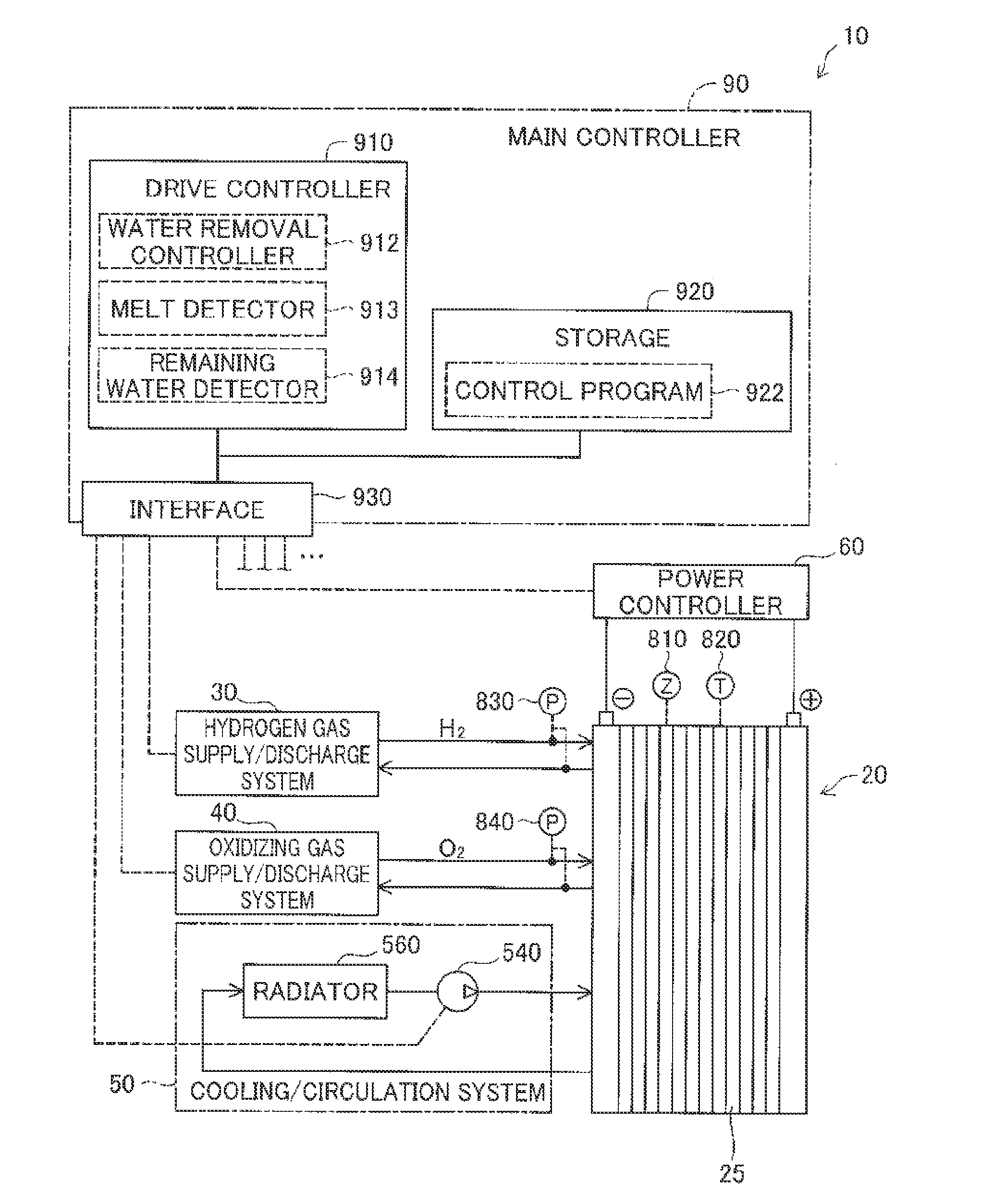
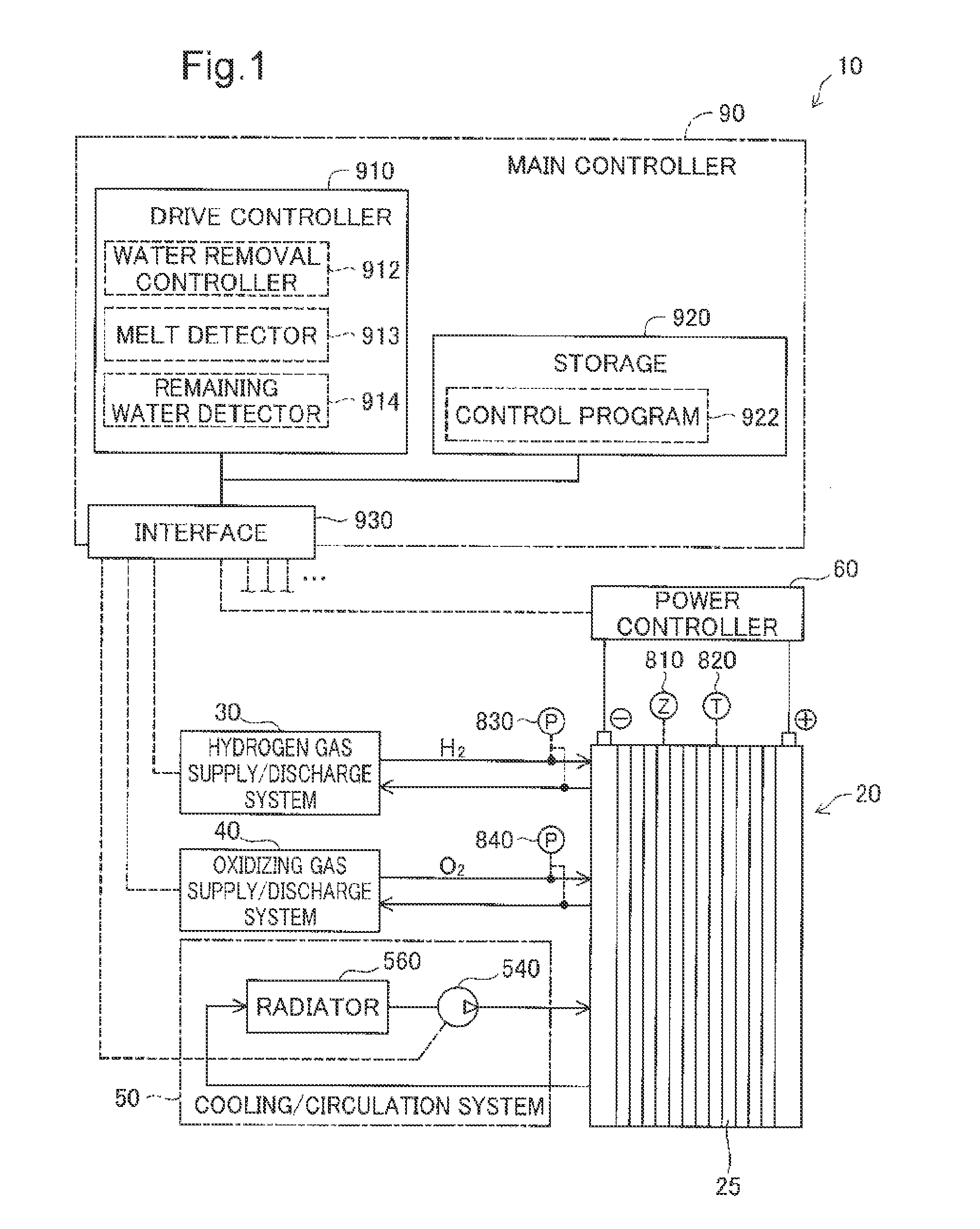
[0042]FIG. 1 illustrates the configuration of a fuel cell system 10. The fuel cell system 10 includes a fuel cell 20 configured to generate electric power through the electrochemical reaction of reactive gases and operates the fuel cell 20 to supply the generated electric power to outside of the fuel cell system 10. According to this embodiment, the fuel cell 20 of the fuel cell system 10 is a polymer electrolyte fuel cell and uses a hydrogen-containing fuel gas and an oxygen-containing oxidizing gas as the reactive gases. The fuel cell system 10 is applied to a system mounted on a vehicle that drives with the electric power generated by the fuel cell 20 according to this embodiment but may also be applicable to a system installed as the power source in a house or a facility and a system incorporated as the power source in electric machine equipment operated with electric power according to other embodiments.
[0043]The fuel cel...
second embodiment
B. Second Embodiment
[0080]The configuration of the fuel cell system 10 according to a second embodiment is similar to that of the first embodiment, except the flow direction of the oxidizing gas in the cathode flow channels 245 during the purge process (step S145). FIG. 8 illustrates the flow directions of the reactive gases according to the second embodiment. More specifically, FIG. 8 shows the flow directions of the reactive gases during ordinary power generation and the flow directions of the reactive gases during the purge process (step S145). During power generation by the fuel cell 20, the flow direction of the hydrogen gas in the anode flow channels 235 is downward along the direction of gravity, i.e., in the same direction as the direction of gravitational force G, while the flow direction of the oxidizing gas in the cathode flow channels 245 is upward along the direction of gravity, i.e., in the opposite direction to the direction of gravitational force G. During the purge ...
third embodiment
C. Third Embodiment
[0082]The configuration of the fuel cell system 10 according to a third embodiment is similar to that of the first embodiment, except the detailed operation of the water removal process (step S140). FIG. 9 is a flowchart showing the details of the water removal process (step S140) according to the third embodiment. The water removal process (step S140) of the third embodiment is similar to that of the first embodiment, except the method of removing the retaining water from the cathode catalyst layer 217. On the start of the water removal process (step S140), the drive controller 910 provides direction to the hydrogen gas supply / discharge system 30 on increasing the stoichiometric ratio of the hydrogen gas in order to increase the amount of water moving from the cathode catalyst layer 217 toward the anode catalyst layer 214 (step S146), while continuing power generation of the fuel cell 20. The stoichiometric ratio of the hydrogen gas represents the ratio of the am...
PUM
 Abstract
Description
Claims
Application Information