Portable sports pod camera mount

Inactive Publication Date: 2010-06-24
ROBINSON ANDY
View PDF18 Cites 43 Cited by
  • Summary
  • Abstract
  • Description
  • Claims
  • Application Information

AI Technical Summary

Benefits of technology

[0016]The inventive concept was spawned by the need arising at organized volleyball tournaments to elevate a video camera, from a very limited platform space. Thus, the camera may be positioned to film the area in the immediate vicinity of the volleyball net,

Problems solved by technology

Further, many monopods, if used with some type of leg attachment, do not support more than 5 or 6 pounds.
Several type

Method used


Image

  • Portable sports pod camera mount
  • Portable sports pod camera mount
  • Portable sports pod camera mount

Examples


Embodiment Construction

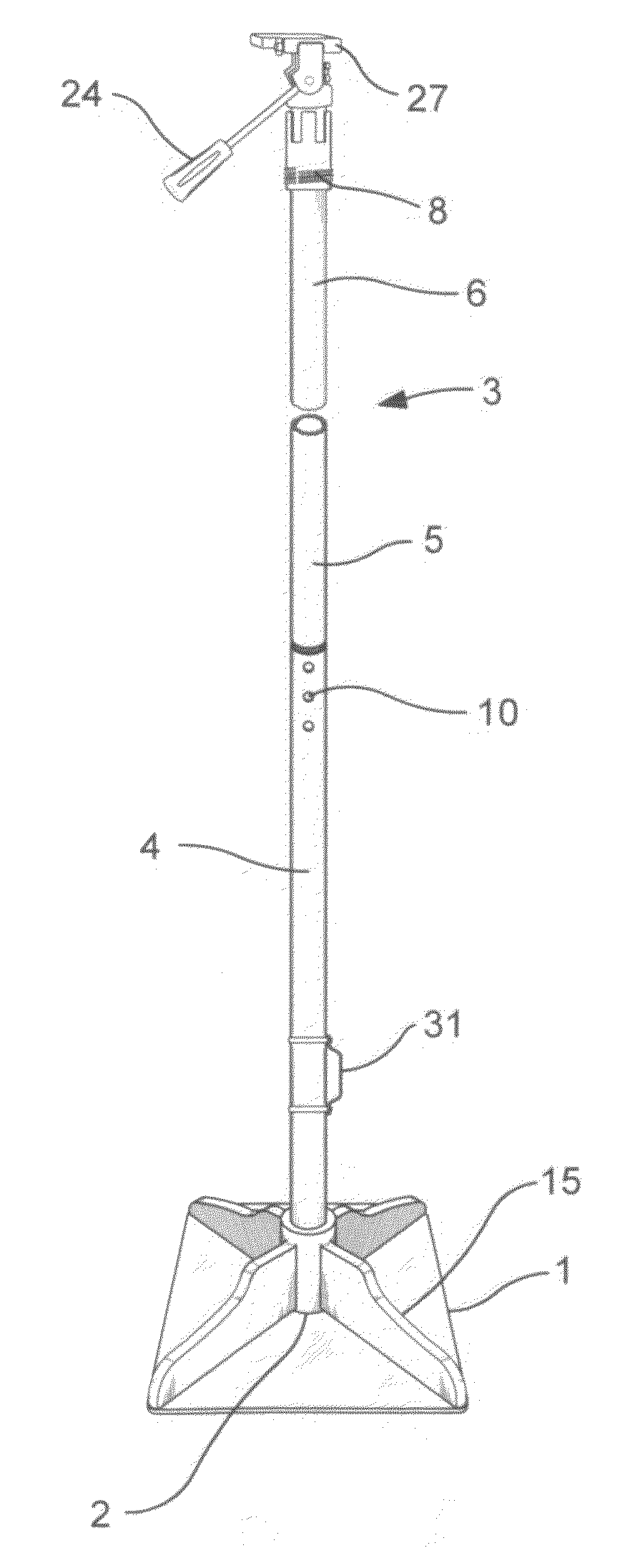
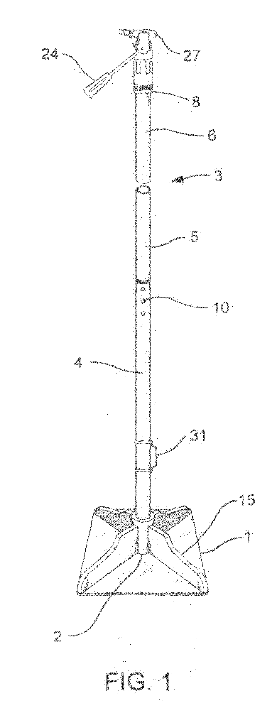
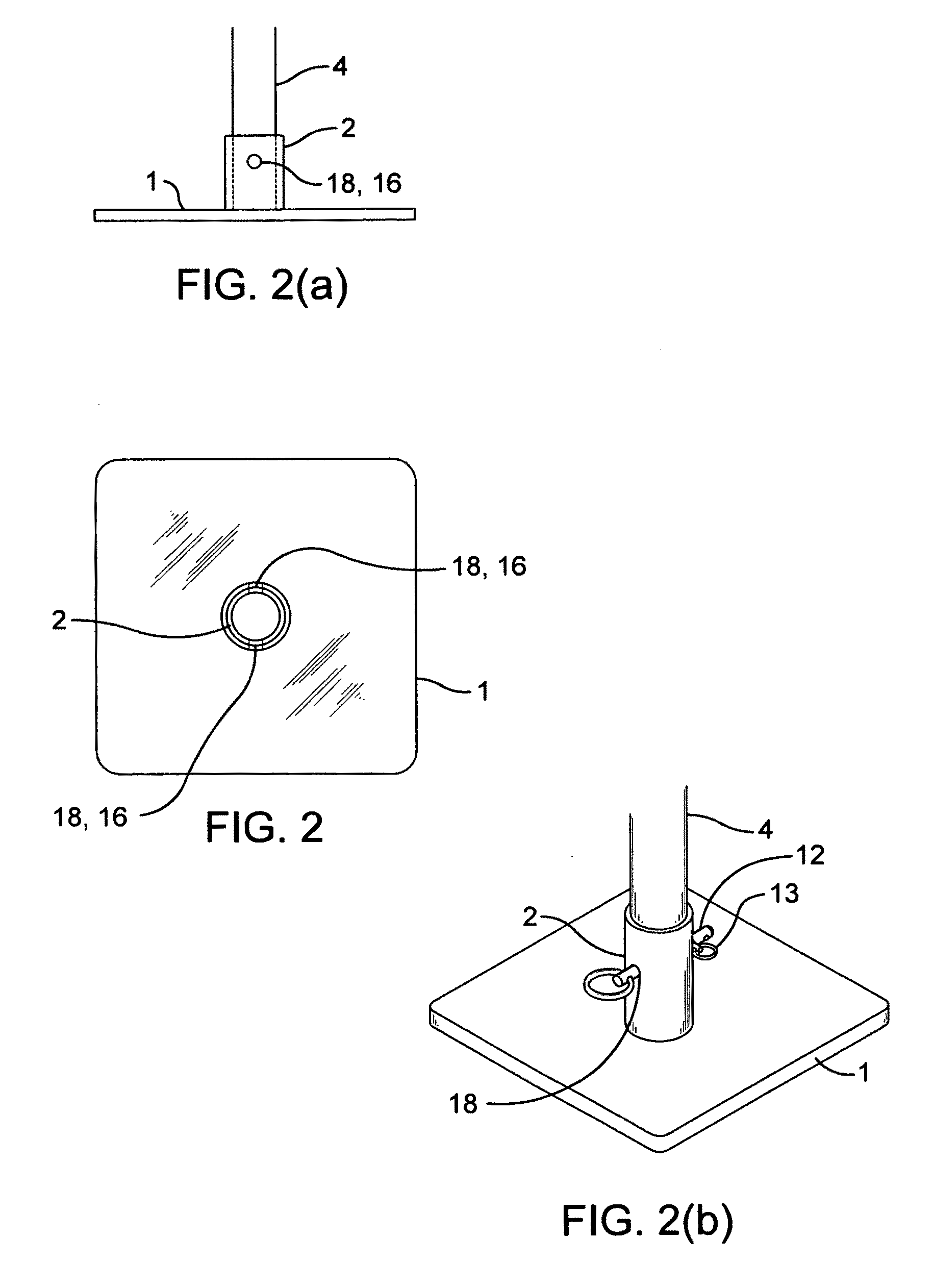
[0069]A description of the inventive concept is best understood in conjunction with reference to the accompanying drawings. The general descriptive flow shall begin at the base of the device and proceed upward. FIG. 1 presents a general view of the inventive concept, depicting a typical weighted base 1 upon which sits, in a vertical orientation relative to the weighted base 1, a segmented pole 3. The lower pole section 4 of the segmented pole 3 rests in a circular sleeve 2 as shown. An additional feature enhancing the portability of the inventive concept is a carry handle 31 shown attached to the lower pole section 4.

[0070]All pole sections are hollow and constructed of a light weight material such as aluminum, fiberglass, or PVC plastic. In FIG. 1 an intermediate pole section 5 is shown, as well as the upper pole section 6. The upper pole section 6 culminates at its top end with the attachment of a mounting table clamp 28 by which a mounting table 27 is affixed for the support of a...


PUM


Abstract

Disclosed is a portable, segmented pole support system used to elevate a camera for recording or photographing action in the area above a volleyball net during game play. The device is capable of supporting an attached camera, video apparatus, monitor, or similar equipment from a secure fitting on a weighted base. Once secured to the pole, the equipment may then be incrementally elevated by extending different sections of the segmented pole to a height exceeding the reach of the device operator. As the court sites change during a multiple-court volleyball tournament, the device may be readily unlocked and compacted into an assembly with an attached carrying handle. The device, being easily portable, may be rapidly set up at each succeeding court location.

Description

CROSS-REFERENCES TO RELATED APPLICATIONSU.S. Patent Documents[0001]U.S. Patent #.Date.ClassificationInventor.4,051,525Sep. 27, 1977358 / 106Kelly, D5,065,249Nov. 12, 1991358 / 229Horn, D.5,786,854Jul. 28, 1998348 / 373Slade, M., et al.6,007,259Dec. 28, 1999396 / 428Mori, A., et al6,056,450May 02, 2000396 / 428Walling, D.6,244,759Jun. 12, 2001396 / 428Russo, R.6,769,824Aug. 03, 2004396 / 419Nakatani, K.7,017,873Mar. 28, 2006248 / 187.1Barth, R.7,344,320Mar. 18, 2008396 / 419Barker, J.U.S. Patent Application Publications[0002]Publication #.Date Published.ClassificationInventor.2006 / 0233544Oct. 19, 2006396 / 428Coppola, R.Foreign Patent Documents[0003]Patent #.Date.ClassificationInventor.WO9747915Dec. 18, 1997G03B17 / 56Frost, R.WO9941540Aug. 19, 1999F16M11 / 10Brown, G.CA2518816Sep. 23, 2004G03B17 / 00Thomas, H. S.WO2006079175Aug. 03, 2006G03B17 / 00Hirano, EOther References[0004]TacView pole camera, version 2600; TacView, Inc. 1300 S. Frazier, Suite Conroe, Tex. 77301[0005]Lynx Camera Mount Pole; Gill Athletics...

Claims


Application Information

Patent Timeline
IPC IPC(8): F16M11/24G03B17/56
CPCF16B7/105F16B7/182F16B9/023F16M11/24G03B17/561F16M11/2014F16M11/28F16M13/00F16M2200/028F16M11/10F16B9/058
Inventor ROBINSON, ANDY
Owner ROBINSON ANDY
Why Eureka
Try Eureka