Apparatus And Methods For The Semi-Automatic Tracking And Examining Of An Object Or An Event In A Monitored Site

a technology of semi-automatic tracking and examining, applied in the field of video surveillance systems, can solve the problems of consuming more, consuming more, and losing highly valuable time, and the job of the human operator watching multiples is tiring and boring,

Active Publication Date: 2010-06-24
QOGNIFY
View PDF75 Cites 92 Cited by
  • Summary
  • Abstract
  • Description
  • Claims
  • Application Information

AI Technical Summary

Benefits of technology

[0012]One aspect of the present invention regards a method for the investigation of one or more objects shown on one or more first displayed video clips captured by a first image capturing device in a monitored site, the method comprising the steps of selecting the object shown on first video clip, the object having a creation time or disappearance time, and displaying a second video clip starting at a pre determined time associated with the creation time of the object within the first video clip or the disappearance time of the object from the first video clip. The second video clip is captured by a second image capturing device. The method further comprising a step of identifying information related to the creation of the object within the first video clip. The method further comprising a step of incorporating the information in multiple frames of the first video clip, in which the at least one object exists. The information comprises the point in time or coordinates at which the object was created within the first video clip. The method further comprising the steps of: recognizing one or more events, based on predetermined parameters, the events involving the object and generating an alarm for the event. The method further comprising a step of constructing a map of the monitored site, the map comprising one or more indications of one or more locations in which image capturing devices are is located. The method further comprising a step of displaying a map of the monitored site, the map comprising one or more indications of one or more locations in which image capturing devices are located. The method further comprising a step of associating the indications with video streams generated by the image capturing devices. The method further comprising a step of indicating on the map the location of an image capturing device, when a clip captured by the image capturing device is displayed. The step of displaying the second video clip further comprises showing the second video clip in forward or backward direction at a predetermined speed. The method further comprising the steps of: defining a first region within the field of view of the first image capturing device; and defining a second region neighboring to the first region, said second region is within a second field of view captured by a second image capturing device. The second video clip is captured by the second image capturing device. The second video clip captured by the second image capturing device is displayed concurrently with displaying the first video clip. The method further comprising the step of displaying the second video clip where the first video clip was displayed, such that the object under investigation is shown on the second video clip. The method further comprising a step of generating one or more combined video clips showing in a continuous manner one or more portions of the first video clip and one or more portions from the second video clip shown to an operator. The method further comprising a step of storing the combined video clip. The predetermined time associated with the creation of the object is a predetermined time prior to the creation of the object. The first or second video clips are displayed in real time or in off-line.

Problems solved by technology

The human operator's tiring and boring job of watching multiple cameras on split screens, when most of the time nothing happens is facilitated by existing techniques.
Therefore, once the operator becomes aware of the attention-requiring situation, some highly valuable time was lost.
The operator can of course playback the relevant stream, but this will consume more, and potentially a lot more valuable time and will not assist in finding the current location and route followed by of the required object, such as the person who abandoned the bag, prior to and following the abandonment.

Method used


Image

  • Apparatus And Methods For The Semi-Automatic Tracking And Examining Of An Object Or An Event In A Monitored Site
  • Apparatus And Methods For The Semi-Automatic Tracking And Examining Of An Object Or An Event In A Monitored Site
  • Apparatus And Methods For The Semi-Automatic Tracking And Examining Of An Object Or An Event In A Monitored Site

Examples


Embodiment Construction

Definitions

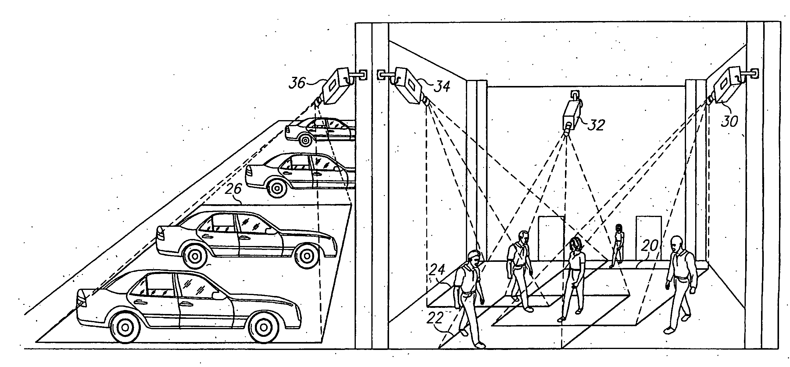
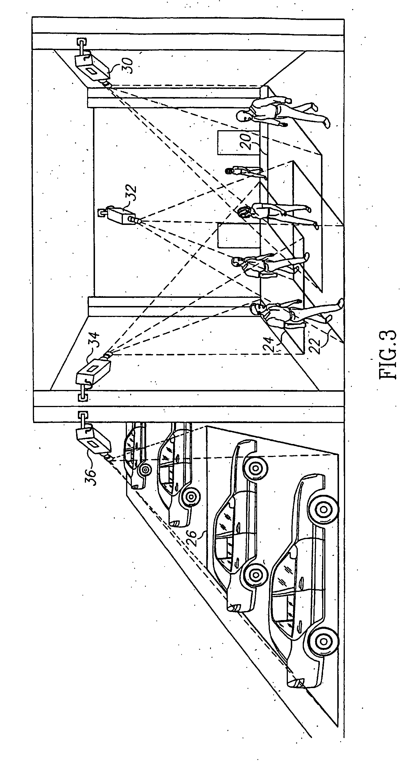
[0022]Image capturing device—a camera or other devices capable of capturing sequences of temporally consecutive images of a location, and producing a plurality or a stream of images, such as a video stream. Close Circuit TV or IP cameras or like cameras are examples of image capturing devices that can be used in a typical environment in which the present invention is used. The produced video streams are monitored or recorded. Such devices can also include X-Ray, Infra-red cameras, or the like.

[0023]Site—an area defined by geographic boundaries monitored by one or more image capturing devices. A site includes one or more sub-areas that can be captured by one or more image capturing devices. A sub-area may be covered by one or more image acquiring device. A sub area may also be outside the area of coverage of an image capturing device. For example, a site in the context of the present invention can be an airport a train or bus station, a secured area that should not be tres...


PUM


Abstract

A method and apparatus for the investigation of an object or an event in a video clip, by playing video clips of the object or objects associated with the events. The video frames comprised within the video clips comprise information regarding the creation time and coordinates of the objects appearing in multiple frames, thus enabling an operator to immediately play video clips tracking the object starting at the object's creation time within the field of view, until its disappearance from the field of view. By defining neighboring regions, and keeping the creation time of each object within each video stream, an object is tracked between different fields of view.

Description

RELATED APPLICATIONS[0001]The present invention is related to PCT application serial number PCT / IL03 / 00097 titled METHOD AND APPARATUS FOR VIDEO FRAME SEQUENCE-BASED OBJECT TRACKING, filed 6 Feb. 2003. The present invention is related to PCT application serial number PCT / IL02 / 01042 titled SYSTEM AND METHOD FOR VIDEO CONTENT-ANALYSIS-BASED DETECTION, SURVEILLANCE, AND ALARM MANAGEMENT, filed 26 Dec. 2002.BACKGROUND OF THE INVENTION[0002]1. Field of the Invention[0003]The present invention relates to video surveillance systems in general, and to an apparatus and method for the semi-automatic examination of the history of a suspicious object, in particular.[0004]2. Discussion of the Related Art[0005]Video surveillance is commonly recognized as a critical security tool. Human operators provide the key for detecting security breaches by watching surveillance screens and facilitating immediate response. For many transportation sites like airports, subways and highways, as well as for othe...

Claims


Application Information

Patent Timeline
Patent Type & Authority Applications(United States)
IPC IPC(8): H04N7/18H04N5/225
CPCG08B13/19608G08B13/19641G08B13/19671G08B13/19693G08B13/19676G08B13/19682G08B13/19673
Inventor DVIR, IGALSHABTAL, MOTI
Owner QOGNIFY
Why Eureka
Try Eureka