
Image processing device and image processing method

a technology of image processing and image, applied in the field of image processing technology, can solve the problems of requiring complex operations, no effective scene change process, difficult to watch video in digest mode, etc., and achieve the effect of reducing the overall length of the outputted video image and reducing the overall length of the video image generated

Inactive Publication Date: 2008-01-24
SEIKO EPSON CORP
View PDF6 Cites 90 Cited by
  • Summary
  • Abstract
  • Description
  • Claims
  • Application Information

AI Technical Summary

Benefits of technology

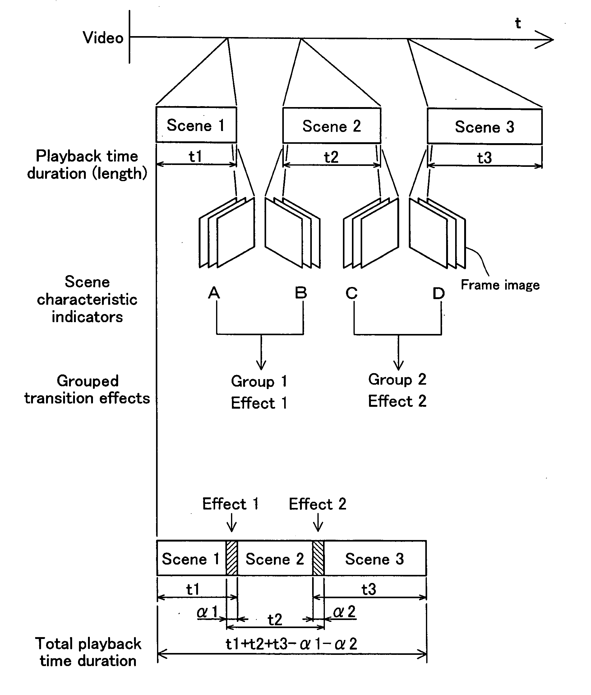
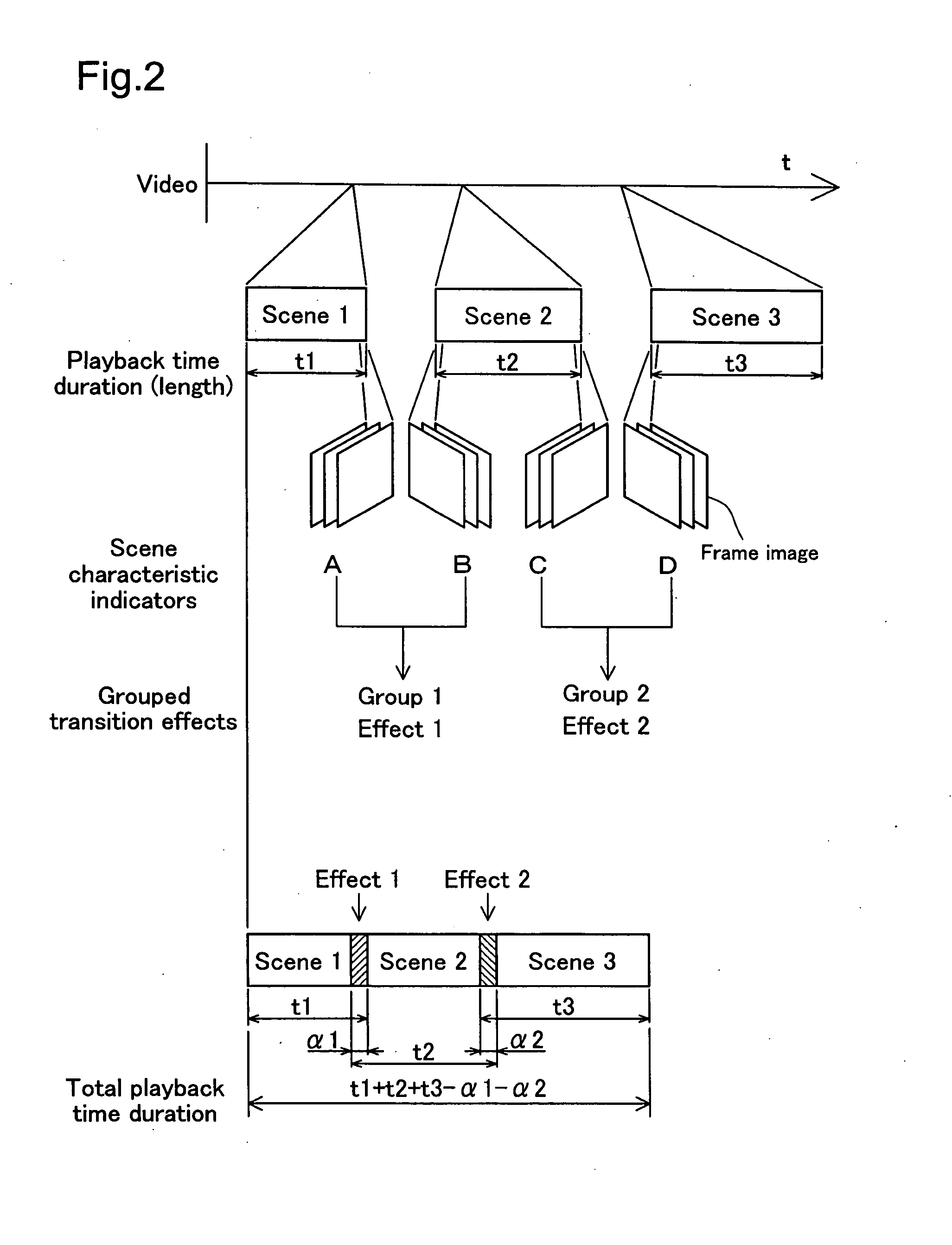
The present invention solves the problem of effectively joining multiple video images together by using a method that stores multiple types of transition effects in advance and selects the appropriate transition effect based on the characteristics of the scenes to be joined together. This method allows for the automatic selection of the transition effect that best matches the scene information, making the scene changes easier to watch. The image processing device uses the method to join together video images by extracting scene information from frame images, detecting the amount of shift between the frames, and calculating the status indicator for the object. The method can be used with a variety of video images and can be adapted based on the patterns of the relationships between the scenes. Overall, this invention provides a more efficient and effective way to join multiple video images together.

Problems solved by technology

However, in this type of digest image, no thought has been given whatsoever to how the various scenes are joined together, so there is a problem in that the digest video is difficult to watch.
One reason for this is that there is no effective process performed for the scene changes because the editing simply joins together various scenes which are unrelated to each other in terms of the content of the video images.
Consequently, in order to effectively join together the various scenes, the user has had to set up transition effects after looking at the earlier and later scenes, requiring complex operations.
Consequently, it is difficult to add new images when the playback time duration for the digest video has been established in advance.

Method used


Image

  • Image processing device and image processing method
  • Image processing device and image processing method
  • Image processing device and image processing method

Examples


first embodiment

A. First Embodiment

[0059] A1. Structure of the Image Processing Device

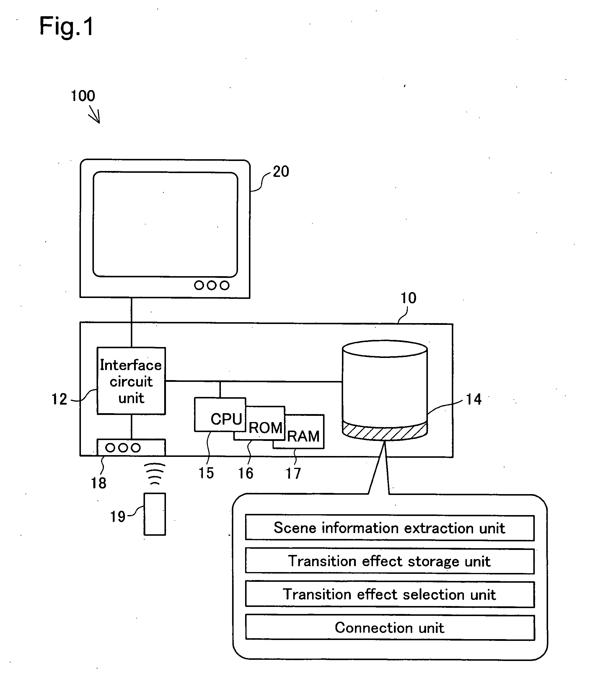
[0060]FIG. 1 is an explanatory figure showing an image processing system 100 that is a first embodiment according to the present invention. As is shown in the figure, this image processing system 100 comprises a hard disk drive (HDD) recorder 10 that records and plays back specific video images, a TV monitor 20 that is connected to the HDD recorder 10 and that displays the video images, and the like.

[0061] The HDD recorder 10 has a variety of functions for editing the stored video images. For example, there is an indexing function that detects automatically changes in scenes in the video image to create an index (with thumbnails) of frame images that represent each scene, and a digest function that extracts a portion of the video image for each scene and that joins together these portions to produce a digest video. This type of automatic detection of scene changes is performed through the detection of changes in...

second embodiment

B. Second Embodiment

[0110] As with the first embodiment, an image processing system according to a second embodiment of the present invention will be explained next. The image processing device according to the second embodiment is an HDD recorder equipped with image processing programs. The HDD recorder in this second embodiment differs from that in the first embodiment only in the image processing programs. Consequently, in terms of the hardware configuration, the same codes as for the image processing system 100 in the first embodiment will be used, and further explanations thereof are omitted. The details of the image processing will be explained.

[0111]FIG. 13 is a flowchart of the image processing in a second embodiment of joining together specific scenes of a video image. The image processing of this second embodiment adds a step wherein a cut change, wherein the scene changes suddenly, is selected in addition to the image processing of the first embodiment. The other steps a...


PUM


Abstract

An image processing device that joins together multiple scenes extracted from a video image, wherein scene information that indicates characteristics of the multiple scenes is extracted from multiple frame images that comprise the video image, where, when two scenes are to be joined together multiple types of transition effects to be used in the changing of the scenes is stored in advance, and a specific transition effect is selected, based on the extracted scene information, from the transition effects that have been stored in advance. For example, effects such as a slide or a wipe are selected based on the characteristics of the video image, such as the direction of movement of an object. The specific transition effect that has been selected is used to join together the two scenes. The result is that it is possible to set up effective scene changes to enable each scene to be joined together.

Description

CLAIM OF PRIORITY [0001] The present application claims priority from Japanese Application P2004-7561A filed in March 2004, the content of which is hereby incorporated by reference into the application. BACKGROUND [0002] 1. Field of the Invention [0003] The present invention relates to image processing technology for joining together multiple scenes extracted from video images. [0004] 2. Description of the Related Art [0005] There has long been the need to be able to understand quickly the contents of lengthy video images. To respond to this need, a variety of methods are used to produce “digest videos” (summaries) by extracting multiple representative scenes (images) from the moving image and joining together these representative scenes. For example, the Patent Document 1, listed below, discloses a technology for producing a summary through detecting the positions of changes in status in images, sounds, subtitles, etc., in the video images for the contents of video images stored on...

Claims


Application Information

Patent Timeline
Patent Type & Authority Applications(United States)
IPC IPC(8): G06K9/36H04N5/91
CPCG06K9/00711G11B2220/2516G11B27/038G11B27/034G06V20/40
Inventor MATSUZAKA, KENJISHINOZAKI, JUNICHIRO
Owner SEIKO EPSON CORP
Learn More